TM 5-3895-382-24
Pump Electrical
Displacement Control (EDC)
Electrical Displacement Control (EDC).
(1) Pressure control plot (PCP) valve. (2) Manual override lever. (3)
Rotary valve. (4) Null adjust screw and locknut (5) Rotary valve cam.
(6) Actuator spool. (7) Modulation spring.
The EDC is a two-stage electrohydraulic control unit. It uses
mechanical feedback and ported control oil to set up a closed
loop swashplate control circuit. The EDC receives electrical
input from the vibratory control rheostat and the vibratory
control switch.
The vibratory selector switch controls the direction of
swashplate angle by sending a current to one of the two coils
inside the EDC. One coil controls the direction of swashplate
angle when the vibratory selector switch is positioned for high
amplitude. The second coil controls the direction of
swashplate angle when the vibratory selector switch is
positioned for low amplitude. The vibratory control rheostat
controls the amount of swashplate angle by controlling the
amount of current sent to the coils.
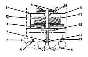
Pressure Control Pilot (PCP) Valve.
(8) Pole piece. (9) Centering springs. (10) Armature. (11) Pole piece.
(12) Magnet. (13) Magnet. (14) Pivot point. (15) Flapper. (16)
Nozzle. (17) Nozzle. (18) Oil supply port. (19) Orifice. (20) Office.
(21) Control port 1. (22) Oil return port. (23) Control port 2.
PCP (1) valve is the first stage of the electrical displacement
control (EDC) unit. The hydraulic portion of the PCP valve is a
closed loop that uses internal hydraulic feedback from the
pump swashplate piston. The PCP electrical section receives
a direct current (DC) input in its torque motor stage. The
torque motor stage of the PCP consists of armature (10),
mounted on the torsion pivot (14) and suspended in a
magnetic field air gap. Magnets (12) and (13) are permanent
magnets of parallel polarity constructed to form a magnetic
bridge.
When the EDC is at null, the armature is centered in the air
gap. The two factors that allow the armature to remain in the
centered position are the equal magnetic forces of the
opposing magnets and centering springs (9). While the
armature is centered, flapper (15) is centered between nozzles
(16) and (17). Upstream from the nozzles are orifices (19) and
(20). In between each orifice and nozzle is a control port.
In the null position, charge oil from the charge pump enters oil
supply port (18) and passes through the two orifices. Because
the flapper is centered between the two nozzles there is no
pressure difference, so an equal amount of the oil flows
through the nozzles, past the flapper and out oil return port
(22).
As current is increased in one direction the end of the armature
becomes polarized either north or south. The armature then
moves towards the opposing magnetic field. The amount of
movement is dependent upon the amount of amperage of the
control current introduced to polo pieces (A1 and (11).
13-26