TM 5-3895-382-24
Clearance between the ends of an oil control ring in a cylinder
liner without any wear .......................................... 0.38 to 0.84 mm
(.015 to .033 inch)
(4)
Diameter of new piston pin .............38.095 to 38.100 mm
(1.4998 to 1.5000 inch)
Bore in piston for pin ....................................38.103 to 38.109 mm
(1.5000 to 1.5004 inch)
Piston height above cylinder block
(not shown) ........................................................... 0.14 to 0.36 mm
(.005 to .014 inch)
Type 2 Engines and 7BJ Engines
NOTE:
For a complete description of Type 1 and Type 2
engines, refer to the Specifications Module,
"Engine Design" for more information.
Illustration 47
NOTE:
The word "Front" or an arrow which is marked on
the piston crown must be toward the front of the
engine. If the piston crown is not marked, put the
narrowest side of the piston crater toward the
side of the engine with the fuel injection pump.
The shortest distance between the edge of the
piston crater and the edge of the piston is the
narrowest side of the piston crater.
NOTE:
Be sure that the ring end gaps of all the piston
rings have 120 degrees spacing from each other.
NOTE:
Refer
to
Systems
Operation,
"General
Information" for the location of the serial number.
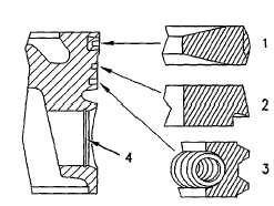
Turbocharged Engines
(1)
Top piston ring
Shape of groove in piston for top ring ..................................Taper
Shape of top ring .....................................................................Taper
Clearance between the ends of the top ring in a cylinder liner
without any wear .................................................. 0.28 to 0.63 mm
(.011 to .025 inch)
NOTE:
Install the word "TOP" toward the top of the
piston. New top rings have a red identification
mark which must be on the left of the ring gap
when the intermediate ring is installed on an
upright piston.
(2)
Intermediate ring
Width of groove in piston for
intermediate ring ................................................... 2.56 to 2.58 mm
(0.101 to 0.102 inch)
Thickness of intermediate ring ........................... 2.48 to 2.49 mm
(0.097 to 0.098 inch)
Clearance between groove and
intermediate ring.................................................... 0.07 to 0.11 mm
(.003 to .004 inch)
Clearance between the ends of an intermediate
ring in a cylinder liner without any
wear ........................................................................ 0.40 to 0.65 mm
(.016 to .026 inch)
NOTE:
Install the word "TOP" toward the top of the
piston. New intermediate rings have a green
identification mark which must be on the left of
the ring gap when the intermediate ring is
installed on an upright piston.
(3)
Oil control ring
Width of groove in piston for oil
control ring ............................................................. 3.54 to 3.56 mm
(.139 to .140 inch)
Thickness of oil control ring ................................ 3.47 to 3.49 mm
(.136 to .137 inch)
Clearance between groove and oil
control ring ............................................................. 0.05 to 0.09 mm
(.002 to .004 inch)
Clearance between the ends of an oil control ring in a cylinder
liner without any wear .......................................... 0.38 to 0.83 mm
(.015 to .033 inch)
NOTE:
A pin is used in order to hold both ends of the
spring of the oil control ring in position. The ends of
the spring of the oil control ring must be 180
degrees opposite the end gap of the oil control ring.
(4)
Diameter of new piston pin..............39.694 to 39.700 mm
(1.5628 to 1.5630 inch)
Bore in piston for pin ....................................39.703 to 39.709 mm
(1.5631 to 1.5633 inch)
Piston height above cylinder block
(not shown) ........................................................... 0.36 to 0.50 mm
(.014 to .020 inch)
5-35