TM 5-3895-382-24
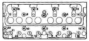
Illustration 18
Bolt tightening sequence for the cylinder head.
Use the following procedure in order to tighten the
cylinder head bolts:
1.
Put engine oil on the threads of the bolts and the nuts.
Tighten bolts (1) through bolts (22) in a numerical
sequence in Illustration 18.
Toque for the bolts .................................110 Nm (81 lb-ft)
2.
Tighten bolts (1) through bolts (2) again in a numerical
sequence.
Torque for bolts ......................................110 Nm (81 lb-ft)
3.
Rotate bolts (1) through bolts (22) in a numerical
sequence to the following values:
a.
Tighten the bolts of short length "S" to the following
value.
Rotate the bolts in a clockwise
direction:....................................................150 degrees
b.
Tighten the bolts of medium length "M" to the
following value.
Rotate the bolts in a clockwise
direction: ...................................................180 degrees
c.
Tighten the bolts of long length "L" to the
following value.
Rotate the bolts in a clockwise
direction:....................................................210 degrees
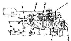
Illustration 19
Bolts, nuts, and components of the cylinder head.
(1)
Tighten the nuts that hold fuel injectors to the
following torque: .......................................12 Nm (10 lb-ft)
NOTE: When the fuel injection nozzle is removed, the
following items must be replaced: dust seal and
seat washer.
(2)
Tighten the nuts for fuel line to the following
torque:.........................................................18 Nm (13 lb-ft)
(3)
Tighten the bolts that hold the rocker shaft to the
cylinder head to the following torque:
Begin tightening the inner bolts. Then tighten the bolts
by working toward the end of the shaft.
Cast iron or steel bracket ................75 Nm (55 lb-ft)
Aluminum bracket ............................40 Nm (30 lb-ft)
(4)
Valve lash
Inlet .......................................................0.20 mm (.008 inch)
Exhaust.................................................0.45 mm (.018 inch)
(5)
Maximum permissible nozzle projection below
cylinder head face after resurfacing ....................4.45 mm
(.175 inch]
Maximum allowance for resurfacing ...............................0.30 mm
................................................................................ (.012 inch)
(6)
Depth of new cylinder head .............102.79 to 103.59 mm
(4.047 to 4.078 inch
Minimum depth of cylinder head after
resurfacing ...................................................................... 102.48 mm
(4.035 inch
5-17