
TM 5-3895-379-23
PROPEL SPEED RANGE SWITCH REPLACEMENT - CONTINUED
0074 00
REMOVAL - CONTINUED
4.
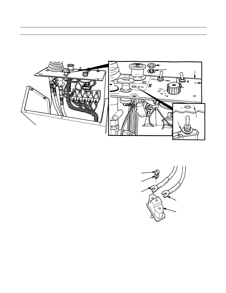
Remove nut (6), lockwasher (7), propel speed range switch (8) and ring (9) from panel assembly (5). Discard lock-
washer.
6
5
7
TAB
NOTCH
8
9
VIEW FROM DRIVER'S SEAT
401-461
NOTE
Tag and mark all wires prior to removal.
5.
Remove two screws (10), lockwashers (11) and
wires (12) and (13) from propel speed range switch
10
(8). Discard lockwashers.
11
13
12
8
401-462
INSTALLATION
1.
Install two wires (12) and (13) on propel speed range switch (8) with new lockwashers (11) and screws (10).
NOTE
Tab of ring fits in notch of panel assembly to properly align propel speed range switch in panel assembly.
2.
Install propel speed range switch (8) on panel assembly (5) with ring (9), new lockwasher (7) and nut (6).
0074 00-2
