
TM 5-3895-379-23
TROUBLESHOOTING PROCEDURES - CONTINUED
0006 00
Table 2. Electrical Troubleshooting Procedures - Continued.
MALFUNCTION
TEST OR INSPECTION
CORRECTIVE ACTION
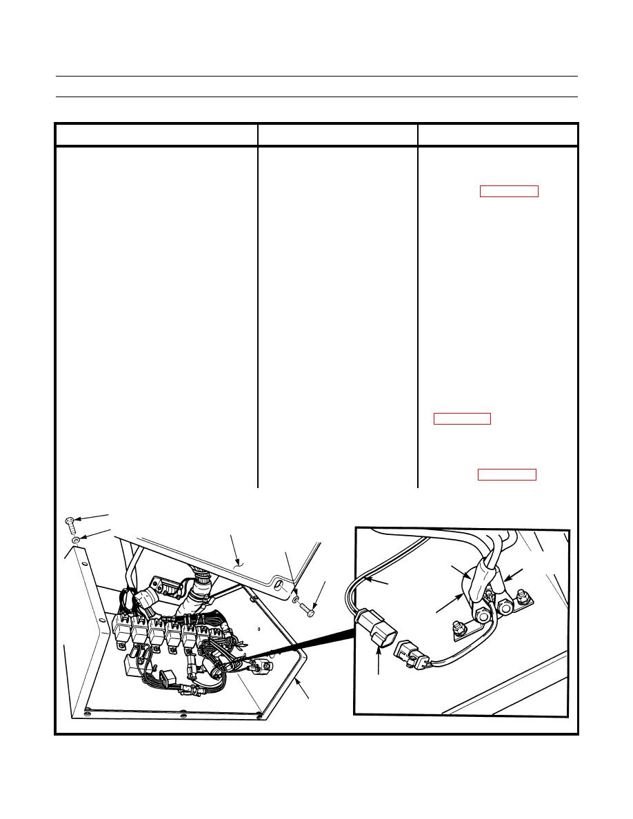
1. Check for power to main relay 1. If 24 to 28 Vdc are not measured
15. No Power to Accessories With The
Engine Running.
from alternator circuit breaker.
at input terminal (wire 109-OR),
Remove nine screws and washers
replace or repair wire 109-OR and
and remove panel from operator
connectors (WP 0108 00).
station. Touch positive (+) probe
of multimeter to input terminal 2. If 24 to 28 Vdc are measured at
input terminal (wire 109-OR), go
(wire 109-OR) and negative (-)
to Step 2.
probe of multimeter to good
ground.
2. Check power to coil of main 1. If 24 to 28 Vdc are not measured
relay. Disconnect main relay
at terminal 1 (wire 308-YL) and
connector
from
harness
KEY START fuse is good, turn
connector. Turn engine start
engine start switch off and go to
switch to ON position (TM 5-
Step 4.
3895-379-10). Touch positive (+)
probe of multimeter to (wire 308- 2. If 24 to 28 Vdc are measured at
terminal 1, go to Step 3.
YL) and negative (-) probe of
multimeter to good ground.
3. Check main relay output. 1. If 24 to 28 Vdc are not measured
Connect main relay connector to
at output terminal of main relay
harness connector. Turn engine
(wire 112-PU), replace main relay
start switch to ON position (TM
5-3895-379-10). Touch positive
(+) probe of multimeter to output 2. If 24 to 28 Vdc are measured at
output terminal of main relay,
terminal of main relay (wire 112-
replace or repair wire 112-PU and
PU) and negative (-) probe of
connectors (WP 0108 00) to fuses.
multimeter to good ground.
SCREW
PANEL
ASSEMBLY
WASHER
WASHER
WIRE
WIRE
112-PU
109-OR
SCREW
WIRE 308-YL
MAIN
RELAY
HARNESS
CONNECTOR
OPERATOR
STATION
401-218
