
TM 5-3895-379-23
TROUBLESHOOTING PROCEDURES - CONTINUED
0006 00
Table 2. Electrical Troubleshooting Procedures - Continued.
MALFUNCTION
TEST OR INSPECTION
CORRECTIVE ACTION
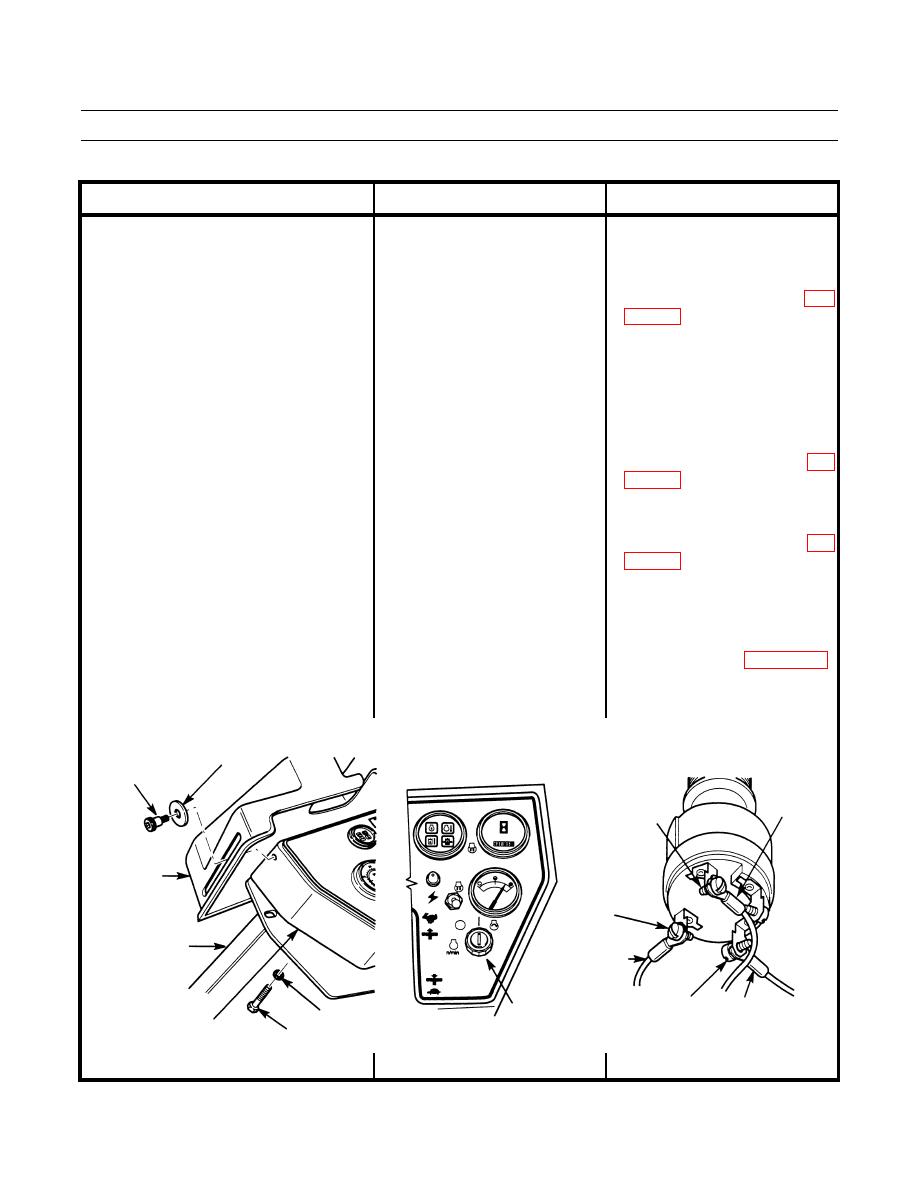
15. No Power to Accessories With The 4. Check for power to engine start 1. If 24 to 28 Vdc are not present at
switch. Remove two shoulder
BAT terminal (wire 105-BR) and
Engine Running - Continued.
screws, washers and vandal guard
KEY START fuse is good, replace
from box assembly. Remove
or repair wiring and connectors to
three screws and washers and lift
KEY START fuse holder (WP
box assembly up from operator
station. Touch positive (+) probe
of multimeter to BAT terminal 2. If 24 to 28 Vdc are present at BAT
terminal, go to Step 5.
(wire 105-BR) of engine start
switch. Touch negative (-) probe
of multimeter to good ground.
5. Check for power output at engine 1. If 24 to 28 Vdc are not present at
start switch. Push propel control
RELAY terminal (wire 103-YL),
lever forward to prevent engine
replace engine start switch (WP
start-up. Touch positive (+) probe
of multimeter to RELAY
terminal (wire 103-YL) of engine 2. If 24 to 28 Vdc are not present at
START terminal (wire 307-OR),
start switch. Touch negative (-)
replace engine start switch (WP
probe of multimeter to good
ground. Turn and hold engine
start switch to start (full right) 3. If 24 to 28 Vdc are present at
position. Measure voltage output.
START and RELAY terminals,
Move positive (+) probe of
replace or repair wiring (wire 103-
multimeter to START terminal
YL or 307-OR) and connectors to
(wire 307-OR) of engine start
engine start switch (WP 0108 00).
switch. Measure voltage. Turn
engine start switch to OFF
position (TM 5-3895-379-10).
SHOULDER
WASHER
SCREW
WIRE
START
307-OR
TERMINAL
VANDAL
BAT
COVER
TERMINAL
OPERATOR
WIRE 105-BR
STATION
RELAY
WIRE
ENGINE
WASHER
TERMINAL 103-YL
COVER
START SWITCH
SCREW
401-219
0006 00-92
