
TM 5-3895-379-23-2
0278
REMOVAL - Continued
5.
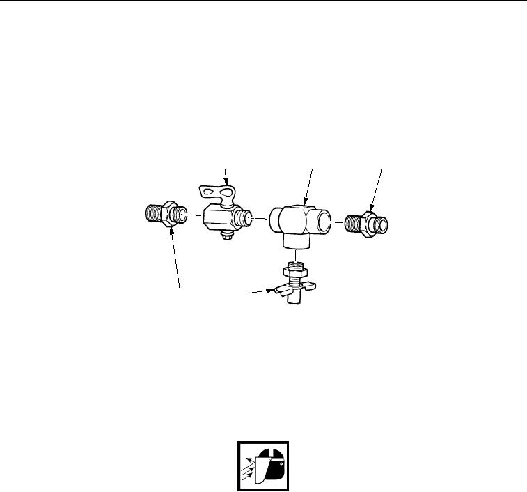
Remove two adapters (Figure 2, Item 3) and tee (Figure 2, Item 2) from valve (Figure 2, Item 1).
6.
Remove drain cock (Figure 2, Item 4) from tee (Figure 2, Item 2).
NOTE
Note position of valve and tee prior to removal.
7.
Remove valve (Figure 2, Item 1) from tee (Figure 2, Item 2) (CB534B Roller).
1
2
3
3
4
M0275SWR
Figure 2. Side Drain Cock and Valve Removal.
END OF TASK
CLEANING
1.
Clean tee, fittings, and drain cock with detergent and water. Remove difficult deposits with a cleaning brush.
WARNING
Particles blown by compressed air are hazardous. DO NOT exceed 15 psi (103 kPa) nozzle
pressure when drying parts with compressed air. Use a maximum of 30 psi (207 kPa) when
cleaning components. DO NOT direct compressed air against human skin. Failure to follow
this warning may cause injury or death. Make sure air stream is directed away from user and
other personnel in the area. To prevent injury, user must wear protective goggles or face
shield.
2.
Use a cleaning cloth or compressed air to dry metal parts.
END OF TASK
03/15/2011Rel(1.8)root(maintwp)wpno(M00216)