
TM 5-3895-379-23-2
0275
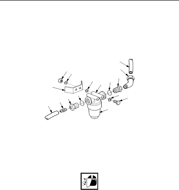
REMOVAL - Continued
2.
Remove tube (Figure 2, Item 11) from connector (Figure 2, Item 10) and tube (Figure 2, Item 7) from elbow
(Figure 2, Item 6).
3.
Remove fluid filter assembly (Figure 2, Item 9) from water filter (Figure 2, Item 3).
4.
Remove two bolts (Figure 2, Item 8), six washers (Figure 2, Item 2), two nuts (Figure 2, Item 1), and water filter
(Figure 2, Item 3) from frame (Figure 2, Item 12).
5.
Remove connector (Figure 2, Item 10), elbow (Figure 2, Item 6), two bushings (Figure 2, Item 5), and two
O-rings (Figure 2, Item 4) from fluid filter (Figure 2, Item 3). Discard O-rings.
7
6
1
2
5
2
4
3
12
2
4
8
5
10
11
9
M0261SWR
Figure 2. Water Spray Screen Assembly Removal.
END OF TASK
CLEANING AND INSPECTION
1.
Clean connector, elbow, bushings, and strainer assembly with detergent and water. Remove difficult deposits
with cleaning brush.
WARNING
Particles blown by compressed air are hazardous. DO NOT exceed 15 psi (103 kPa) nozzle
pressure when drying parts with compressed air. Use a maximum of 30 psi (207 kPa) when
cleaning components. DO NOT direct compressed air against human skin. Failure to follow
this warning may cause injury or death. Make sure air stream is directed away from user and
other personnel in the area. To prevent injury, user must wear protective goggles or face
shield.
2.
Use a cleaning cloth or compressed air to dry metal parts.
3.
Check connector, elbow, and bushings for clogging, corrosion, or excessive wear.
4.
Check fluid filter assembly for clogging, corrosion, excessive wear, and obvious signs of damage.
03/15/2011Rel(1.8)root(maintwp)wpno(M00213)