
TM 5-3895-379-23-2
0265
INSTALLATION - Continued
11.
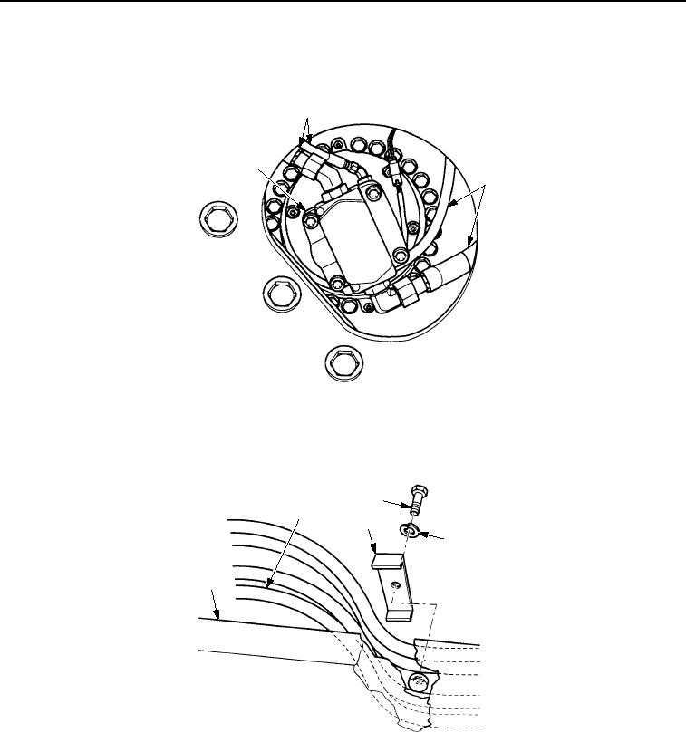
Connect four hose assemblies (Figure 13, Item 2) to vibratory motor (Figure 13, Item 1).
2
1
2
M0224SWR
Figure 13. Drum Assembly Installation.
12.
Install bolt (Figure 14, Item 3), washer (Figure 14, Item 4), and clamp (Figure 14, Item 2) that fasten hose
assemblies (Figure 14, Item 1) to yoke (Figure 14, Item 5).
3
1
2
4
5
M0225SWR
Figure 14. Drum Assembly Installation.
03/15/2011Rel(1.8)root(maintwp)wpno(M00203)