
TM 5-3895-379-23-2
0265
REMOVAL - Continued
WARNING
Oil is very slippery. Immediately wipe up any spills. Failure to follow this warning may cause
injury.
CAUTION
Cap and plug all lines and fittings to prevent any contaminants from entering the system.
Tag and mark all hydraulic lines and electrical wires as they are removed or disconnected.
Use container to capture any hydraulic oil which may drain from lines. Dispose of
hydraulic oil IAW local policy and ordinances.
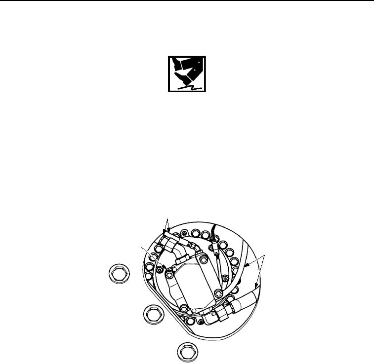
4.
Disconnect four hose assemblies (Figure 4, Item 2) from vibratory motor (Figure 4, Item 1). Cap and plug hoses
and ports immediately. Move hose assemblies aside.
2
1
2
M0216SWR
Figure 4. Drum Assembly Removal.
5.
Remove bolt (Figure 5, Item 5), washer (Figure 5, Item 4), and clamp (Figure 5, Item 3) that fasten hose
assemblies (Figure 5, Item 9) to drum support (Figure 1, Item 1).
6.
Remove bolt (Figure 5, Item 12) and clamp (Figure 5, Item 1) that fasten hose assemblies (Figure 5, Item 9)
to yoke (Figure 5, Item 2).
7.
Remove all ties, bolt (Figure 5, Item 11), two washers (Figure 5, Item 8), nut (Figure 5, Item 7), and clamp
(Figure 5, Item 6) from frame (Figure 5, Item 10). Discard ties.
03/15/2011Rel(1.8)root(maintwp)wpno(M00203)