
TM 5-3895-379-23-2
0264
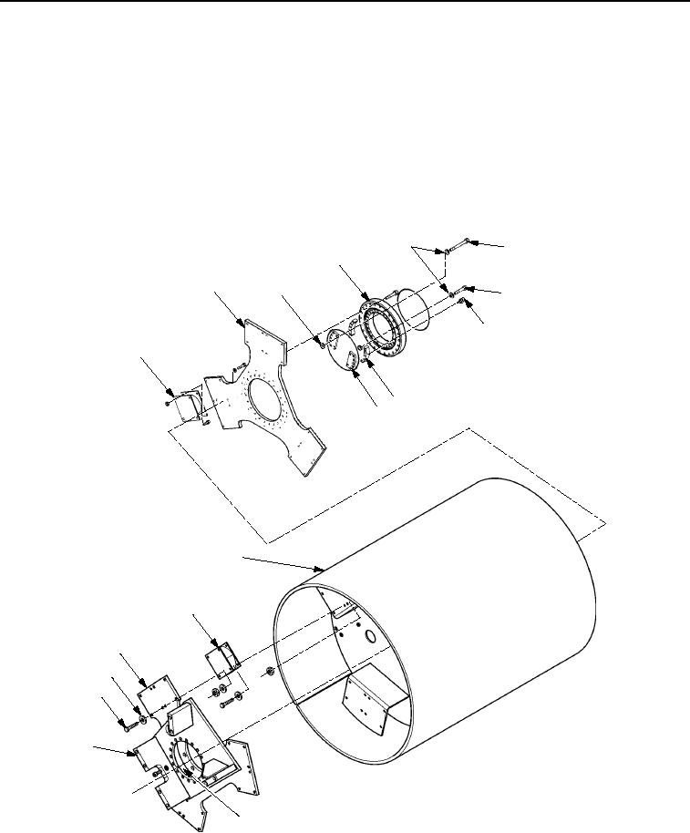
DRUM ASSEMBLY - Continued
10.
Install two fittings (Figure 11, Item 8), 24 bolts (Figure 11, Item 7), washers (Figure 11, Item 5), nuts
(Figure 11, Item 9), and bearing assembly (Figure 11, Item 10) to plate (Figure 11, Item 2).
11.
Use two persons to install supports (Figure 11, Item 11) and (Figure 11, Item 4) to plate (Figure 11, Item 2).
12.
Install 25 new locknuts (Figure 11, Item 3), washers (Figure 11, Item 5), and bolts (Figure 11, Item 6).
13.
Attach lifting device straps to plate (Figure 11, Item 2) and support (Figure 11, Item 11). Remove 24 bolts
(Figure 11, Item 12) and washers (Figure 11, Item 13) that fasten plate (Figure 11, Item 2) to mounts
(Figure 11, Item 1) and remove plate (Figure 11, Item 2) and support (Figure 11, Item 11), as a unit, to drum
assembly (Figure 11, Item 14).
5
6
4
2
3
7
8
1
9
10
14
1
2
13
12
11
4
M0212SWR
Figure 11.
Drum Assembly.
END OF TASK
03/15/2011Rel(1.8)root(maintwp)wpno(M00202)