
TM 5-3895-379-23-2
0247
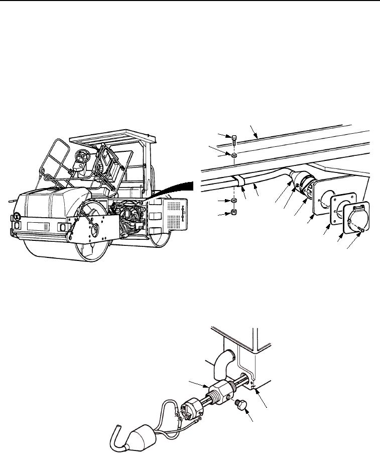
INSTALLATION
1.
Install seal (Figure 4, Item 6), receptacle cover (Figure 4, Item 5), two screws (Figure 4, Item 4), receptacle
(Figure 4, Item 8), and two new locknuts (Figure 4, Item 9) on bracket (Figure 4, Item 7).
2.
Slide boot (Figure 4, Item 10) on cable (Figure 4, Item 11) to cover two locknuts (Figure 4, Item 9).
3.
Install cable (Figure 4, Item 11) into three clips (Figure 4, Item 12).
4.
Install three washers (Figure 4, Item 1), screws (Figure 4, Item 2), clips (Figure 4, Item 12), washers
(Figure 4, Item 1), and nuts (Figure 4, Item 13) to frame assembly (Figure 4, Item 3).
3
2
1
12 11 10
1
9
13
8
7
6
5
4
M1136SWR
Figure 4. Engine Block Heating Element Installation.
5.
Install drain plug (Figure 5, Item 3) into engine block fitting (Figure 5, Item 1).
6.
If removed, install engine block fitting (Figure 5, Item 1) into engine block (Figure 5, Item 2).
1
2
3
M1135SWR
Figure 5. Engine Block Heating Element Installation.
03/15/2011Rel(1.8)root(maintwp)wpno(M00185)