
TM 5-3895-379-23-2
0247
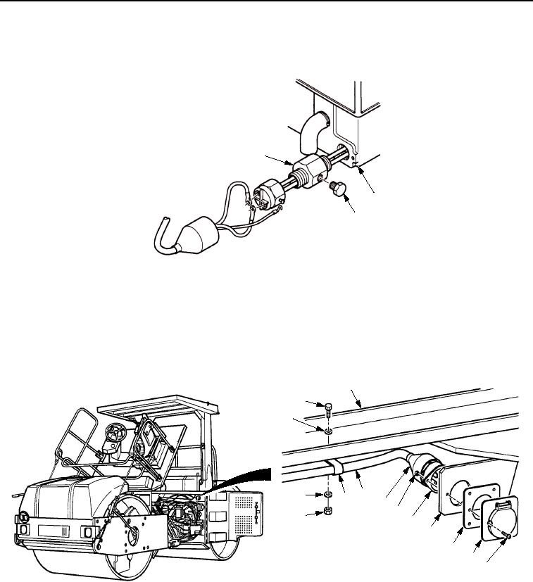
REMOVAL - Continued
6.
Remove engine block fitting (Figure 2, Item 1) from engine block (Figure 2, Item 2).
1
2
3
M0810SWR
Figure 2.
Engine Block Heating Element Removal.
7.
Remove three nuts (Figure 3, Item 13), washers (Figure 3, Item 1), clips (Figure 3, Item 12), screws
(Figure 3, Item 2), and washers (Figure 3, Item 1) from frame assembly (Figure 3, Item 3).
8.
Slide boot (Figure 3, Item 10) on cable (Figure 3, Item 11) back to expose two locknuts (Figure 3, Item 9).
9.
Remove two locknuts (Figure 3, Item 9), receptacle (Figure 3, Item 8), two screws (Figure 3, Item 4), receptacle
cover (Figure 3, Item 5), and seal (Figure 3, Item 6) from bracket (Figure 3, Item 7). Discard locknuts.
3
2
1
12 11 10
1
9
13
8
7
6
5
4
M0811SWR
Figure 3.
Engine Block Heating Element Removal.
END OF TASK
03/15/2011Rel(1.8)root(maintwp)wpno(M00185)