
TM 5-3895-379-23-2
0244
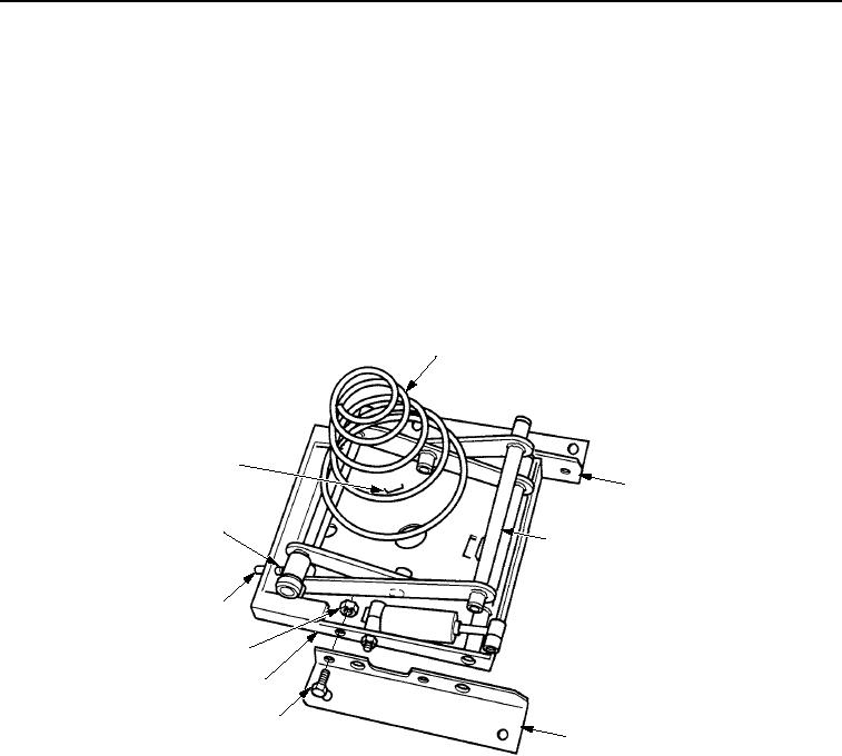
ASSEMBLY - Continued
13.
Slide indicator (Figure 18, Item 10) into spring pin (Figure 18, Item 9) while installing arm (Figure 18, Item 4)
in lower housing assembly (Figure 18, Item 7).
14.
Apply sealing compound to threads of four bolts (Figure 18, Item 6).
15.
Install left-hand angle (Figure 18, Item 5) and right-hand angle (Figure 18, Item 3) on lower housing assembly
(Figure 18, Item 7) with four bolts (Figure 18, Item 6) and new locknuts (Figure 18, Item 8). Tighten nuts to
84-192 lb-in. (9-22 Nm).
16.
Install shaft (Figure 21, Item 1) in lower housing assembly (Figure 18, Item 7) and arm (Figure 18, Item 4) with
new push on nut (Figure 21, Item 3).
17.
Install spring (Figure 18, Item 2) in lower housing assembly (Figure 18, Item 7) by compressing and turning
spring clockwise until spring is securely seated in three tabs (Figure 18, Item 1).
2
1
3
10
4
9
8
7
6
5
M0796SWR
Figure 18.
Seat Suspension Assembly.
03/15/2011Rel(1.8)root(maintwp)wpno(M00182)