
TM 5-3895-379-23-2
0222
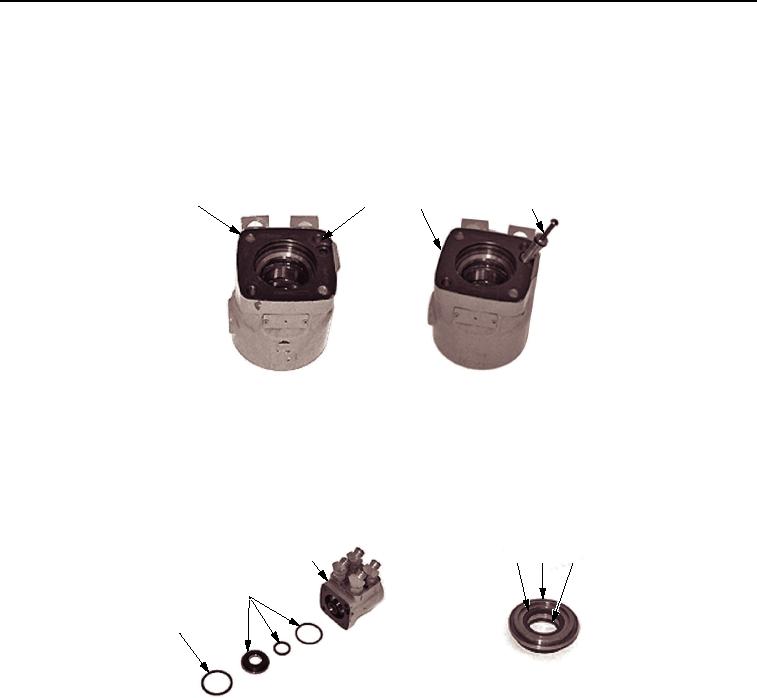
ASSEMBLY - Continued
NOTE
After installation, the set screw should be slightly below the outside surface of the center
housing.
5.
Install setscrew (Figure 11, Item 2) in control housing (Figure 11, Item 3) and tighten to 8 lb-in. (11 Nm).
1
2
3
4
M0676SWR
Figure 11. Steering Control Unit (SCU) Assembly.
6.
Assemble gland bushing (Figure 12, Item 2). Install new dust seal (Figure 12, Item 4) in seal gland bushing
(Figure 12, Item 5) with the flat or smooth side of seal facing bushing and turn seal gland bushing over. Install
new quad ring seal (Figure 12, Item 6) in the seal gland bushing. Smooth seal in place with finger.
7.
Install gland bushing assembly (Figure 12, Item 2) in control housing (Figure 12, Item 3) and secure with new
retaining ring (Figure 12, Item 1).
3
4
5
6
2
1
M0677SWR
Figure 12. Steering Control Unit (SCU) Assembly.
03/15/2011Rel(1.8)root(maintwp)wpno(M00160)