
TM 5-3895-379-23-1
0219
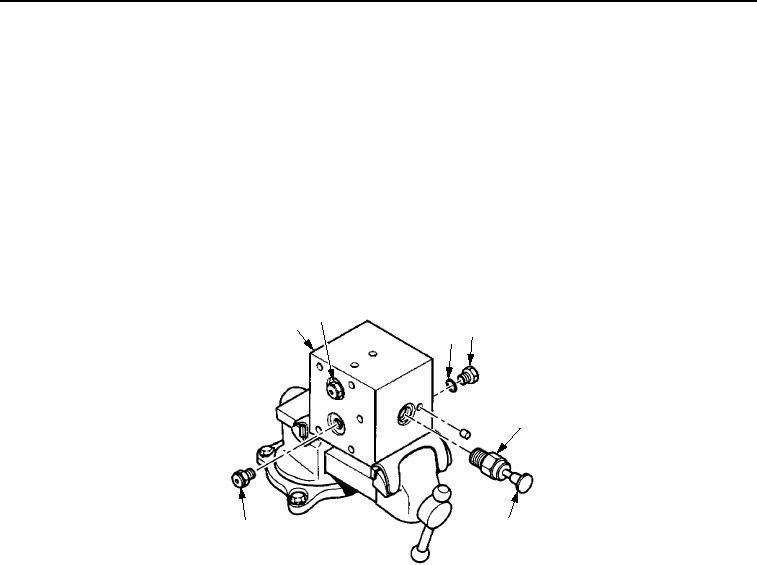
ASSEMBLY
1.
Place manual brake release pump (Figure 6, Item 1) in soft-jawed vise.
2.
On CB534B Roller, install expansion plug (Figure 6, Item 7) in manual brake release pump (Figure 6, Item 1).
3.
Install new O-ring (Figure 6, Item 3) (CB534C) and plug (Figure 6, Item 4) in manual handle release pump
(Figure 6, Item 1).
4.
Install two check valves (Figure 6, Item 2) in manual brake release pump (Figure 6, Item 1).
5.
On CB534B Roller, lubricate area of hand pump (Figure 6, Item 6) that will be located inside the manual brake
release pump (Figure 6, Item 1) with clean lubricating oil.
6.
On CB534B Roller, install hand pump (Figure 6, Item 6) in manual brake release pump (Figure 6, Item 1) and
tighten nut (Figure 6, Item 5).
2
1
3 4
5
6
7
M0650SWR
Figure 6.
Manual Brake Release Pump Assembly.
END OF TASK
03/15/2011Rel(1.8)root(maintwp)wpno(M00157)