
TM 5-3895-379-23-1
0199
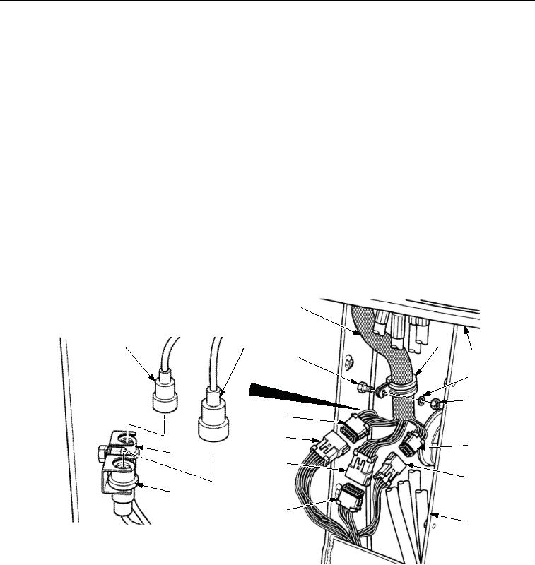
REMOVAL - Continued
5.
Remove locknut (Figure 3, Item 8), washer (Figure 3, Item 7), and clamp (Figure 3, Item 5) from operator station
stud (Figure 3, Item 3). Discard locknut.
NOTE
Tag and mark all wires prior to removal.
Remove cable ties as required for removal of wiring harness assembly.
6.
Remove clamp (Figure 3, Item 5) from instrument wiring harness assembly (Figure 3, Item 4).
7.
Disconnect connector (Figure 3, Item 9) from connector (Figure 3, Item 10).
8.
Disconnect connector (Figure 3, Item 13) from connector (Figure 3, Item 12).
9.
Disconnect connector (Figure 3, Item 17) from connector (Figure 3, Item 16).
10.
Disconnect connector (Figure 3, Item 2) from connector (Figure 3, Item 13).
11.
Disconnect connector (Figure 3, Item 1) from connector (Figure 3, Item 14).
12.
Carefully lift instrument box assembly (Figure 3, Item 6) and instrument wiring harness assembly
(Figure 3, Item 4) from operator station (Figure 3, Item 11) and place on work bench.
4
1
2
5
6
3
7
8
15
16
9
14
17
10
13
12
11
M0329SWR
Figure 3. Instrument Wiring Harness Removal.
13.
Remove lamp assembly (Figure 4, Item 6) from Vibrations Per Minute (VPM) tachometer (Figure 4, Item 7).
14.
Remove three nuts (Figure 4, Item 1), wires (Figure 4, Items 4, 5, and 10), and lockwashers (Figure 4, Item 3)
from VPM tachometer terminals (Figure 4, Items 2, 8, and 9). Discard lockwashers.
03/15/2011Rel(1.8)root(maintwp)wpno(M00137)