
TM 5-3895-379-23-1
0168
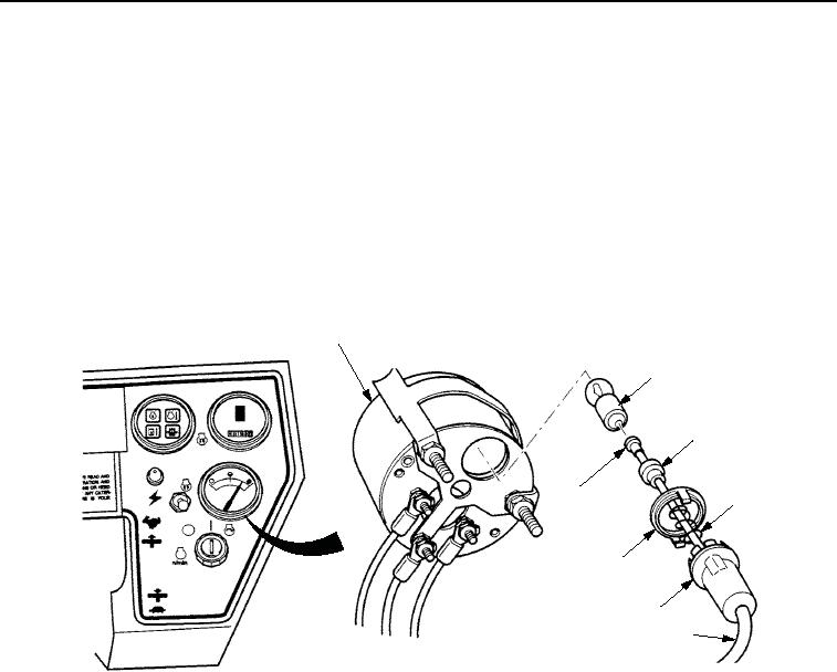
INSTALLATION - Continued
NOTE
Perform Steps (6) and (7) only if wire was cut.
6.
Install light fixture (Figure 9, Item 6), spring (Figure 9, Item 4), and cap (Figure 9, Item 3) on wire
(Figure 9, Item 5).
7.
Solder contact (Figure 9, Item 8) on wire (Figure 9, Item 5).
8.
Push and twist light bulb (Figure 9, Item 2) clockwise and install light bulb in light fixture (Figure 9, Item 6).
9.
Install retainer clip (Figure 9, Item 7) on light fixture (Figure 9, Item 6).
10.
Push light fixture (Figure 9, Item 6) and install light fixture in fuel level gauge (Figure 9, Item 1).
1
2
3
8
4
7
6
5
M1055SWR
Figure 9. Fuel Level Gauge Installation.
03/15/2011Rel(1.8)root(maintwp)wpno(M00106)