
TM 5-3895-379-23-1
0154
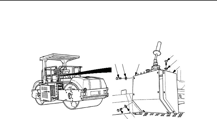
INSTALLATION - Continued
4.
Install panel assembly (Figure 4, Item 3) on operator station (Figure 4, Item 4) with two washers
(Figure 4, Item 5), seven washers (Figure 4, Item 2), and nine screws (Figure 4, Item 1).
1
2
1
2
3
4
5
1
M0851SWR
Figure 4.
Main Relay Installation.
END OF TASK
FOLLOW-ON MAINTENANCE
1.
Close right-side door assembly. (TM 5-3895-379-10)
2.
Remove chocks. (TM 5-3895-379-10)
END OF TASK
END OF WORK PACKAGE
03/15/2011Rel(1.8)root(maintwp)wpno(M00092)