
TM 5-3895-379-23-1
0148
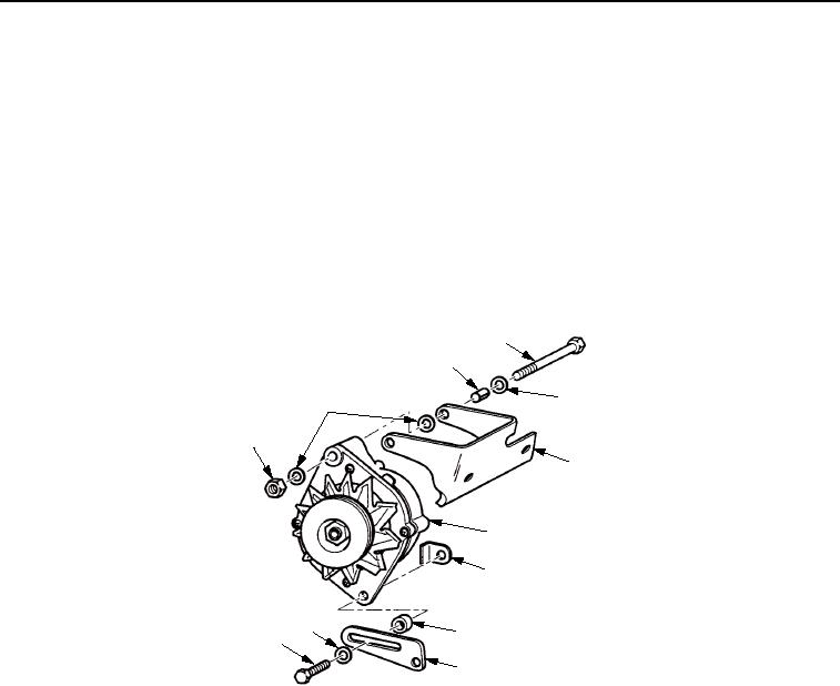
INSTALLATION
NOTE
Ensure alternator pulley is aligned with crankshaft pulley to within 3/32 in. (2.4 mm).
If alternator pulley is removed, install alternator pulley on alternator and tighten alternator
nut to 48-55 lb-ft (65-75 Nm).
1.
With assistance, install alternator (Figure 4, Item 6) on alternator bracket (Figure 4, Item 5) with screw
(Figure 4, Item 4), washer (Figure 4, Item 2), spacer (Figure 4, Item 3), washer (Figure 4, Item 2), and nut
(Figure 4, Item 1). Do not tighten nut.
2.
Install alternator (Figure 4, Item 6) on alternator strap (Figure 4, Item 9), and welded nut (Figure 4, Item 7) with
spacer (Figure 4, Item 8), washer (Figure 4, Item 11), and screw (Figure 4, Item 10). Do not tighten nut.
4
3
2
2
1
5
6
7
11
8
10
9
M0831SWR
Figure 4.
Alternator Installation.
3.
Install two wires (Figure 5, Item 1), new lockwasher (Figure 5, Item 4), and nut (Figure 5, Item 5) on terminal
B+ (Figure 5, Item 3) of alternator (Figure 5, Item 2).
03/15/2011Rel(1.8)root(maintwp)wpno(M00086)