
TM 5-3895-379-23-1
0136
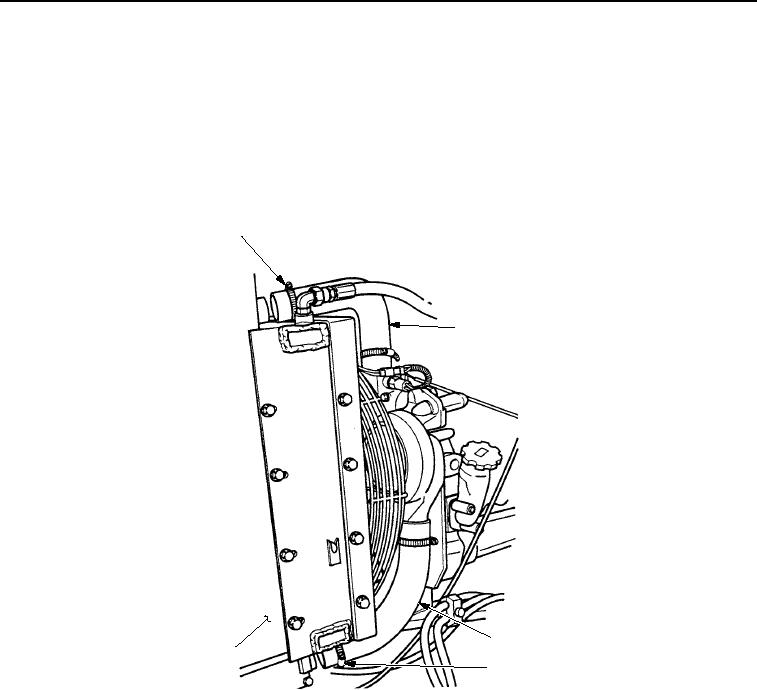
INSTALLATION - Continued
9.
Slide clamp (Figure 4, Item 4) over bottom radiator hose (Figure 4, Item 3).
10.
Position bottom radiator hose (Figure 4, Item 3) on radiator (Figure 4, Item 5) and tighten clamp
(Figure 4, Item 4).
11.
Slide clamp (Figure 4, Item 1) over top radiator hose (Figure 4, Item 2).
12.
Position top radiator hose (Figure 4, Item 2) on radiator (Figure 4, Item 5) and tighten clamp
(Figure 4, Item 1).
1
2
3
5
4
M0617SWR
Figure 4. Radiator Assembly Installation.
END OF TASK
03/15/2011Rel(1.8)root(maintwp)wpno(M00074)