
TM 5-3895-379-23-1
0131
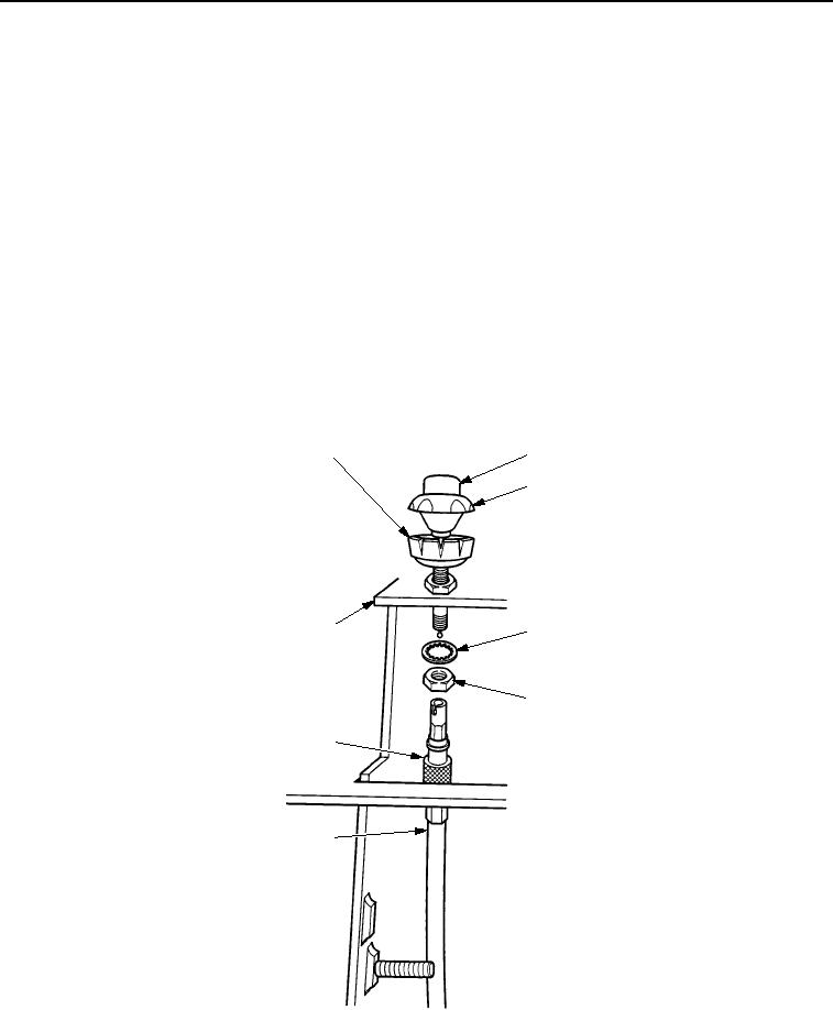
INSTALLATION
1.
Guide throttle cable (Figure 10, Item 6) through operator station (Figure 10, Item 8).
2.
Position throttle cable handle (Figure 10, Item 3) on operator station (Figure 10, Item 8).
3.
Position new lockwasher (Figure 10, Item 4) and new locking nut (Figure 10, Item 5) on throttle cable handle
(Figure 10, Item 3).
4.
Install throttle cable handle (Figure 10, Item 3) on throttle cable (Figure 10, Item 6) and tighten knurled nut
(Figure 10, Item 7).
CAUTION
Do not tighten locking nut more than 120 lb-in. (14 Nm) or damage will occur to throttle cable
handle.
5.
Tighten locking nut (Figure 10, Item 5) and lockwasher (Figure 10, Item 4) on throttle cable handle
(Figure 10, Item 3).
6.
Tighten friction lock (Figure 10, Item 1) on throttle cable handle (Figure 10, Item 3) with throttle cable handle
pushed down as far as possible.
2
1
3
8
4
5
7
6
M1265SWR
Figure 10. Throttle Cable Installation.
03/15/2011Rel(1.8)root(maintwp)wpno(M00069)