
TM 5-3895-379-23-1
0131
REMOVAL - Continued
8.
Lower operator platform assembly (Volume 2, WP 0235).
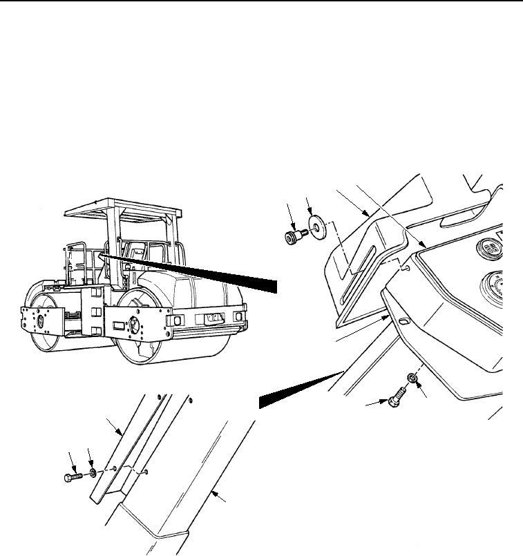
9.
Remove two shoulder screws (Figure 6, Item 1), washers (Figure 6, Item 2), and vandal guard
(Figure 6, Item 3) from instrument box assembly (Figure 6, Item 4).
10.
Remove four screws (Figure 6, Item 8), washers (Figure 6, Item 9), and cover (Figure 6, Item 10) from operator
station (Figure 6, Item 7).
11.
Remove three screws (Figure 6, Item 6) and washers (Figure 6, Item 5) from operator station
(Figure 6, Item 7) and instrument box assembly (Figure 6, Item 4).
4
3
2
1
7
5
6
10
9
8
7
M0590SWR
Figure 6.
Throttle Cable Removal.
03/15/2011Rel(1.8)root(maintwp)wpno(M00069)