
TM 5-3895-379-23-1
0127
FUEL FILTER ASSEMBLY INSTALLATION - Continued
6.
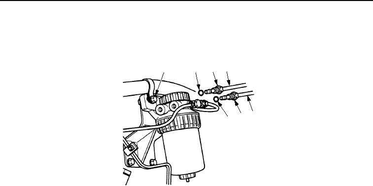
Install two new bushings (Figure 13, Items 2 and 7) and tubes (Figure 13, Items 4 and 5) in fuel filter assembly
(Figure 13, Item 1) and tighten two nuts (Figure 13, Items 3 and 6).
4
3
1
2
5
6
7
M0562SWR
Figure 13. Fuel Filter Assembly Installation.
7.
Ensure that drain valve (Figure 14, Item 4) on bottom of filter element (Figure 14, Item 3) is closed. If drain
valve is open, close drain valve.
8.
If removed, install two new washers (Figure 14, Item 8) and adapters (Figure 14, Item 7) in fuel injection pump
(Figure 14, Item 5).
9.
Install two new bushings (Figure 14, Items 16 and 17), two new bushings (Figure 14, Item 6), and two tubes
(Figure 14, Items 12 and 13) in fuel filter assembly (Figure 14, Item 18) and on two adapters
(Figure 14, Item 7). Tighten two nuts (Figure 14, Items 14 and 15) and two nuts (Figure 14, Item 9).
10.
Slide clamp (Figure 14, Item 10) up and tighten nut (Figure 14, Item 11).
11.
For CB534B Roller, open fuel supply valves (Figure 14, Item 1).
12.
For CB534C Roller, open fuel supply valves (Figure 14, Item 2).
03/15/2011Rel(1.8)root(maintwp)wpno(M00065)