
TM 5-3895-379-23-1
0078
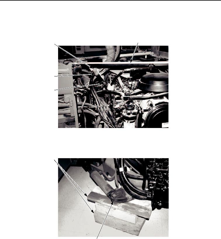
INSTALLATION - Continued
37.
Install clamp (Figure 45, Item 4) on brace assembly (Figure 45, Item 2) with two bolts (Figure 45, Item 1) and
nuts (Figure 45, Item 3).
2
1
4
3
M0049SWR
Figure 45. Engine Assembly Installation.
38.
Remove two wooden blocks (Figure 46, Item 1) from under each steering cylinder mount (Figure 46, Item 2).
1
2
M0050SWR
Figure 46. Engine Assembly Installation.
END OF TASK
03/15/2011Rel(1.8)root(maintwp)wpno(M00017)