
TM 5-3895-379-23-1
0048
MALFUNCTION
Propel Speed Switch or Shift Solenoid Control Wire Faulty.
CORRECTIVE ACTION
1.
Touch positive (+) probe of multimeter to wire 751-GN.
2.
Touch negative (-) probe of multimeter to good ground.
3.
Turn engine start switch to OFF position (TM 5-3895-379-10).
4.
Turn battery disconnect switch to OFF position (TM 5-3895-379-10).
a.
If 24 to 28 VDC are not measured at wire 751-GN, replace propel speed switch
b.
If 24 to 28 VDC are measured at wire 751-GN, repair or replace wire 751-GN and connectors
from propel switch to brake control valve (WP 0195).
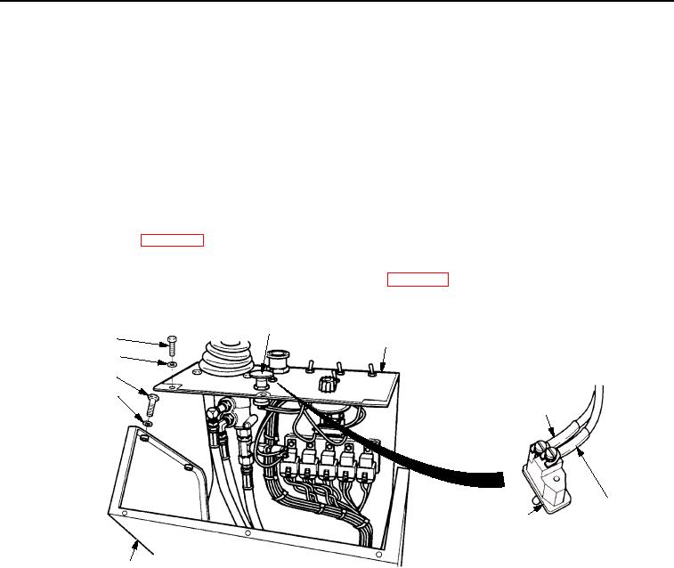
PROPEL SPEED
RANGE SWITCH
SCREW
PANEL ASSEMBLY
WASHER
SCREW
WASHER
WIRE 751-GN
WIRE
PROPEL SPEED
155-PK
SWITCH
OPERATOR STATION
T0129SWR
Figure 4. Propel Speed Switch Wiring.
END OF WORK PACKAGE