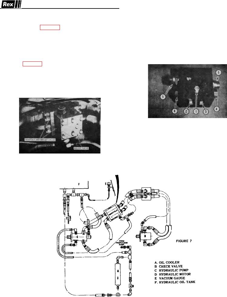
REFERENCE FOR FIGURE 7B
HYDRAULIC SYSTEMS
NO 1 - CHARGE PRESSURE GAUGE PORT
NO 2 - HIGH PRESSURE GAUGE PORT FOR
1 Vibrator Control Figure 7 The vibrator control system
ITEM 6
consists of a positive displacement axial piston pump
NO 3 - HIGH PRESSURE GAUGE PORT FOR
coupled to the engine flywheel, a positive displacement
ITEM 5
gear type motor coupled to the eccentric drive on the
NO 4 - SHUTTLE VALVES
roller shaft, hydraulic lines and vibrator control on the
NO 5 - HIGH PRESSURE RELIEF VALVE
operator's console
NO 6 - HIGH PRESSURE RELIEF VALVE
2 Traction. Figure 8 The hydrostatic drive Vibratory Roller
consists of a diesel engine for power, a variable
displacement piston type pump which is connected to the
engine crankshaft. A fixed displacement, piston type
motor is coupled to the two-speed case on the axle
differential, hydraulic lines, oil reservoir, filter, oil cooler
and controls.
FIGURE 7B
FIGURE 7A
13

