
3.0 Specifications
DETROIT DIESEL 53
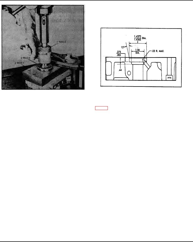
Fig. 3 - Positioning Cutting Tool in Fixture Guide
Fig. 4 - End Plate Oil Drain Back Counterbore
4. Install tool holder J 9533-2 in the drill press and insert the rough cutting tool J 9533-3 in the holder (Fig. 2).
5. Position the cutting, tool in the fixture guide as shown in Fig. 3. Operate the drill press at 75-100 rpm so as to center
the cutting tool in the rotor shaft hole. Tighten the clamp.
6. Lubricate the cutting tool and the area of the end plate that is being reworked with a lubricant (oleum or fuel oil).
7. Operate the drill press at 300-350 rpm and slowly counterbore the hole until the collar of the tool holder is
approximately 1/16 " from the fixture guide. Then reduce the speed of the drill press to 75-100 rpm and continue
counterboring until the collar contacts the top of the guide.
NOTE: Raise the cutting tool periodically during the drilling operation and apply additional lubricant.
8. Stop the drill press and remove the rough cutting tool.
9. Insert the finish cutting tool J 9533-4 in the holder. Lubricate the cutting tool and the end plate. Operate the drill
press at 75-100 rpm and finish-cut the counterbore. Feed the cutting tool into the work slowly.
10. Remove the finish cutting tool anti install an end mill to machine the additional 1.06 " diameter counterbore. The
total depth of the combined counterbores is .44 " (Fig. 4). The additional counterbore provides proper oil drain back front
the oil seal area.
11. Remove the fixture from the end plate. Wipe the cuttings from the end plate and fixture and dry the plate and
fixture with compressed air. Remove any burrs from the edge of the oil hole.
12. Thoroughly clean the cutting tool and the end mill flutes and repeat the procedures for the adjacent rotor shaft hole.
13. Place the blower end plate on the bed of an arbor press. Use installer J 22576 to press the seal (lip facing down)
into the counterbored hole until the shoulder on the installer contacts the end plate.
NOTE: A step under the shoulder of the installer will position the oil seal below the finished face of the end plate
within the .002 " to .008" specified.
Steel Inserts
To install steel inserts in the blower end plates, follow Steps I through 9 and II and 12. Press the inserts flush to .003 "
above the blower end plate surface.
Page 2