
DETROIT DIESEL
Engine Tune Up
LIMITING SPEED MECHANICAL GOVERNOR AND INJECTOR RACK
CONTROL ADJUSTMENT
IN-LINE ENGINES
The double-weight limiting speed governor is mounted on the rear end plate of the engine and is driven by a gear that
extends through the end plate and meshes with either the camshaft gear or the balance shaft gear, depending upon the
engine model. After adjusting the exhaust valves and timing the fuel injectors, adjust the governor and position the
injector rack control levers.
NOTE: Before proceeding with the governor and injector rack adjustments,
disconnect any supplementary governing device. After the adjustments are
completed, re-connect and adjust the supplementary governing device.
Adjust Governor Gap
With the engine stopped and at operating temperature, adjust the governor gap as follows:
1.
Remove the high-speed spring retainer cover.
2.
Back out the buffer screw (Fig. 8) until it extends approximately 5/8" from the lock nut.
3.
Start the engine and adjust the idle speed screw (Fig. 7) to obtain the desired engine idle speed. Hold the screw
and tighten the lock nut to hold the adjustment.
NOTE: The recommended idle speed for non-EPA certified engines is 500-600 rpm, but may
vary with special engine applications.
4.
Stop the engine, clean and remove the govern or cover and the valve rocker cover. Discard the gaskets. 5. Start
and run the engine, between 800 and 1000 rpm by manual operation of the injector control tube lever.
CAUTION: Do not over speed the engine.
6.
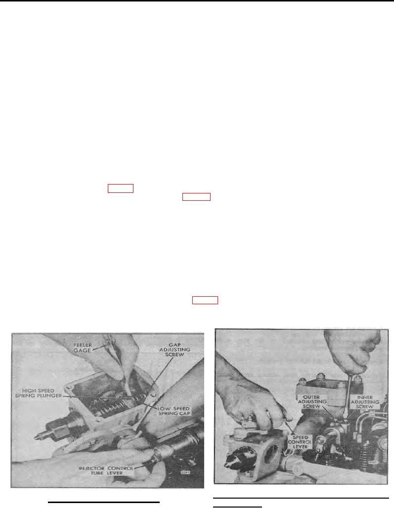
Check the gap between the low-speed spring cap and the high-speed spring plunger with a .0015 " feeler gage. If
the gap setting is incorrect, reset the gap adjusting screw (Fig. 1). If the setting is correct, the.0015" movement can be
seen by placing a few drops of oil into the governor gap and pressing a screwdriver against the gap adjusting screw.
Movement of
Fig. 2.
Positioning the Rear Injector Rack
Fig. 1. Adusting Governor Gap
Control Lever
Page 79