SECTION 9
STEERING
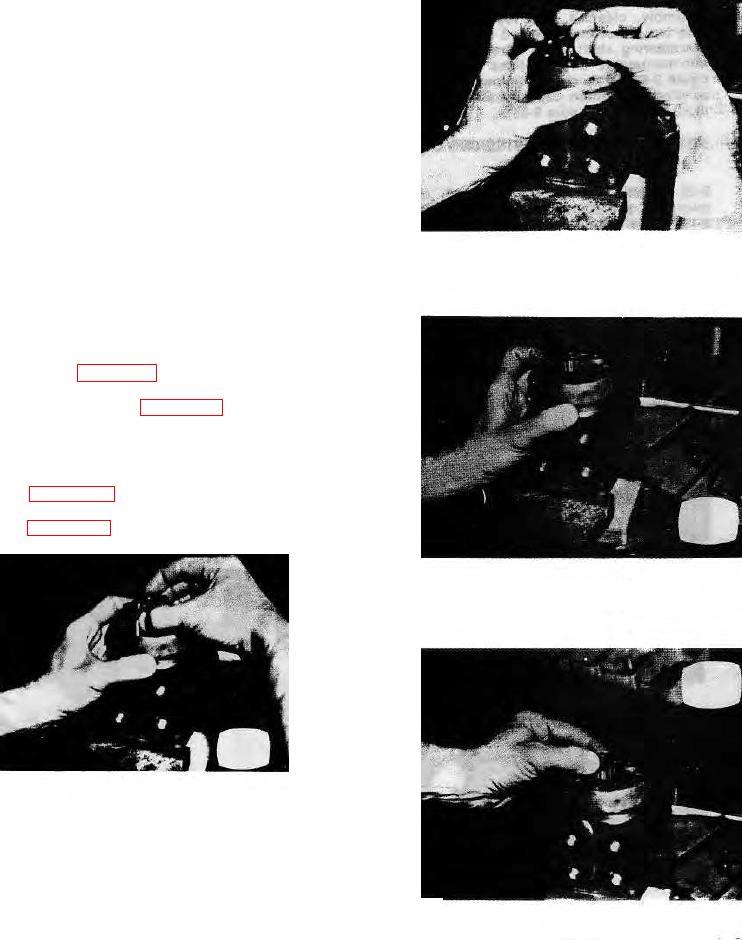
through the gear so that the spline extends about one half
its length beyond the meter gear star and hold It in this
position while installing into the unit. Note the position or
direction of the cross pin within the unit. Enter the meter
gear star into the meter gear ring and wiggle the parts
slowly in position so that the drive does not become
disengaged from the meter gear star. Hold the plate and
meter gear ring in position on the assembly while the star
is being installed. Rotate the meter gear star slightly to
bring the cross slot of the drive into engagement with the
cross pin and the splined end of the drive will drop down
against the plate (see figures 9-58, 9-59 and 9-60).
WARNING: Alignment of the cross slot in the drive with
valleys between the teeth of the meter gear
star determines proper valve timing of the
FIGURE 9-59
unit. There are 12 teeth on the spline and 6
pump teeth on the star. Alignment is exactly
right in 6 positions and exactly wrong in 6
positions. If the parts slip out of position
during this part of assembly, repeat until you
are certain correct alignment is obtained (see
u. Place the spacer in position within the end of the
meter gear star (see figure 9-61). If the spacer does not
drop flush with the gear surface, the drive has not
properly engaged the cross pin - RECHECK. Place the
meter end cap over the assembly and install two (2)
capscrews, finger tight, to maintain alignment of the parts
(see figure 9-62). Install all seven capscrews and bring
them gradually and evenly to 12.5 ft.-lbs. (1.728 kg-m)
(see figure 9-63).
FIGURE 9-60
FIGURE 9-58
9-16.
FIGURE 9-61

