
SECTION 9
STEERING
FIGURE 9-54
FIGURE 9-52
q. Reposition in vise and clamp across the edges of
the mounting plate lightly. Check to insure that the spool
and sleeve are flush or slightly below the 14 hole surface
of the control housing (see figure 9-53).
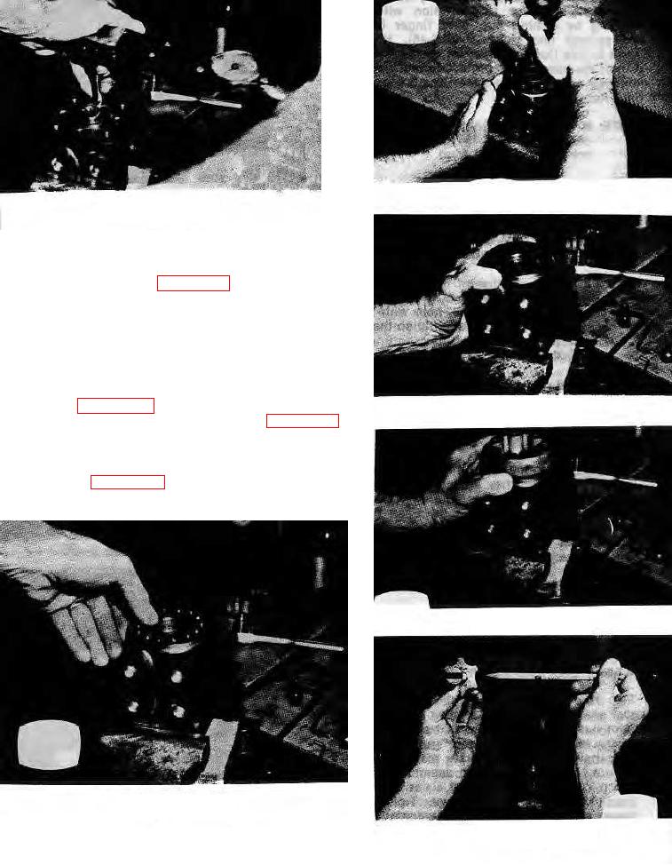
r. Clean the upper surface of the housing by wiping
with the back of a clean hand or the butt of the thumb.
Clean each of the flat surfaces of the meter section parts
as it is ready for assembly in a similar way (see figure 9-
54).
s. Place the plate over this assembly so that the
bolt- holes in the plate-align-with the tapped holes in the
housing (see figure 9-55). Place the meter gear ring on
FIGURE 9-55
the assembly so that the bolt holes align (see figure 9-56).
t. Place the splined end of the drive within the
meter gear star so that the slot at the control end of the
drive is in alignment with the valleys between the meter
gear teeth (see figure 9-57). Push the splined end of the
drive
FIGURE 9-56
FIGURE 9-53
FIGURE 9-57
9-15.