
SECTION 7
TRANSMISSION
c. Start the engine and increase speed to 1500
high-pressure oil.
RPM. The gauge should indicate 190 to 220 PSI (13.36
to 15.47 kg/cm2) above case pressure with oil at
7-154. LOW-CHARGE-PRESSURE RELIEF VALVE.
operating temperature. If. the pressure is not within the
7-155. The low-charge-pressure relief valve works with
specified limits, troubleshoot the system as specified in
the shuttle valve to control pressure in the charge circuit
and to remove excess oil to the cooling circuit. This
valve will allow additional oil to dump if the high-
7-160. CHECKING LOW CHARGE PRESSURE
pressure relief valves cannot dump fast enough under
excessive conditions. Excess oil will be ported through
(see figure 7-38).
the drain circuit to the oil cooler. It is operative only
7-161. The low charge pressure should be between 150
when the transmission is not in neutral.
and 180 PSI (10.55 and 12.66 kg/cm2) above case
pressure with oil at operating temperature, when the
transmission is operating in forward or reverse. The low
7-156. PRESSURE CHECKS.
charge pressure relief valve is located in the motor
7-157.
Pressure
checks
are
imperative
in
manifold as shown in figure 7-38. Check the pressure as
troubleshooting the hydraulic system.
follows:
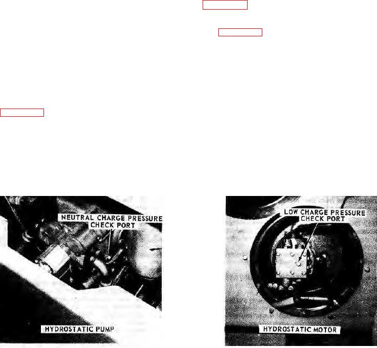
a. Remove the threaded plug from the Low Charge
7-158. CHECKING NEUTRAL CHARGE PRESSURE
Pressure Check Port. Install a 600 PSI (40 kg/cm2)
(see figure 7-37).
gauge equipped with a short section of hose. Use an o-
7-159. Neutral charge pressure can be checked at the
ring adapter in the port. Make sure that the gauge is
transmission pump as follows:
accurately calibrated.
a. Remove the threaded plug from the charge
b. Block the drive drum safely off the ground and
pressure port. Install a 600 PSI (40 kg/cm2) gauge
start the engine.
equipped with a short section of hose. Make sure the
c. Increase engine speed to 1500 RPM. Move the
gauge is accurately calibrated.
Direction-Throttle Control Bail slightly to
NOTE: Use a 7/16 x 20 o-ring adapter in the port.
b. Place the Direction-Throttle Control Bail in
neutral.
FIGURE 7-37.
FIGURE 7-38.
7-30.