Home
Download PDF
Order CD-ROM
Order in Print
Fig. 16 - Schematic Diagram of Typical In-Line Engine Lubricating System
Fig. 18 - Typical Cooling System for In-Line Engines
Maintenance Manual For Roller, Pneumatic Tired Variable Pressure, Self-Propelled (Cce)
Page Navigation
265
266
267
268
269
270
271
272
273
274
275
DETROIT
DIESEL
Engine
Systems
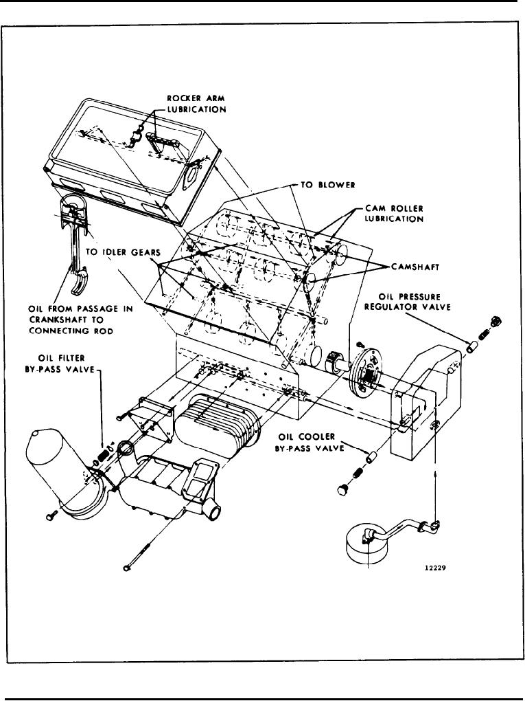
Fig.
17 -
Schematic
Diagram
of
Typical
6V
Engine
Lubricating
System
Page
24