TM 5-3895-346-14
FUEL PUMP
ENGINE OVERHAUL
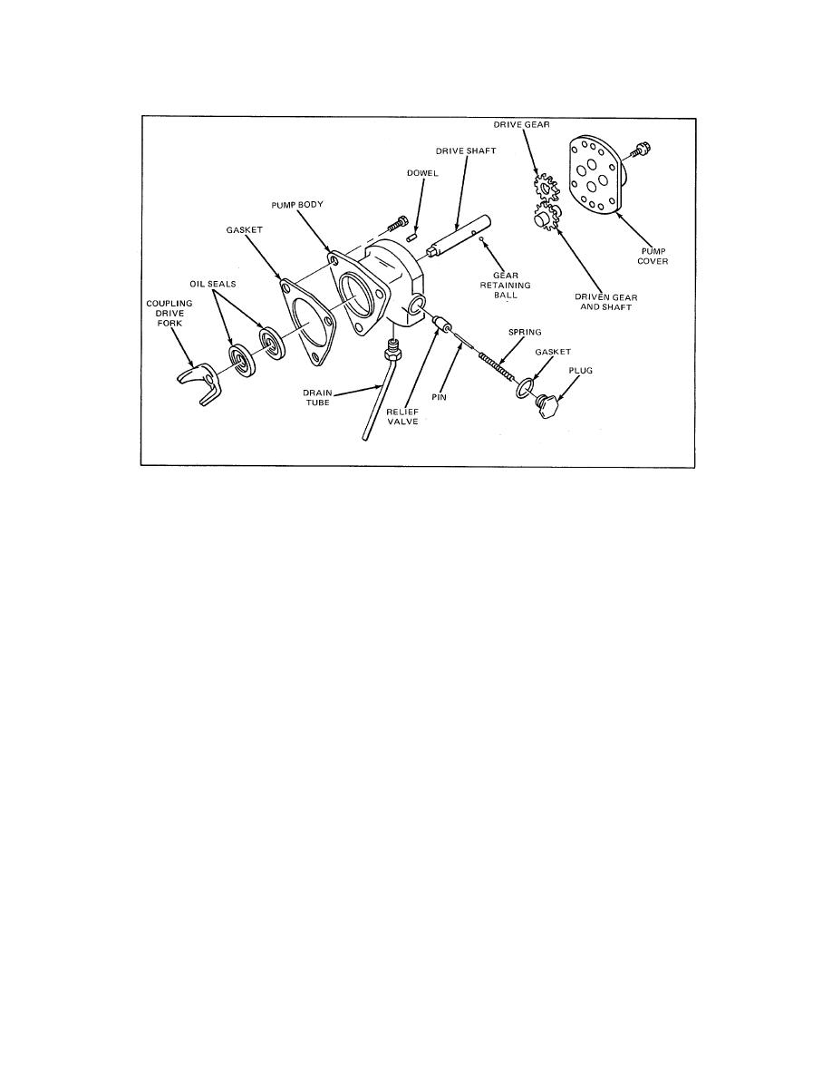
Figure 5. Fuel Pump Details and Relative Location of Parts (Right Hand Pump Shown)
Place the outer oil seal on the pilot of the installer handle with the lip of the seal facing the adaptor. Then insert
the pilot of the installer handle into the pump body and drive the seal in (Fig. 7) until the shoulder of the adaptor
contacts the pump body. The oil seals will be positioned so that the space between them will correspond with
the drain holes located in the bottom of the pump body.
2. Clamp the pump body in a bench vise (equipped with soft jaws) with the valve cavity up. Lubricate the
outside diameter of the valve and place it in the cavity with the hollow end up. Insert the spring inside of the
valve and the pin inside of the spring. With a new gasket in place next to the head of the valve plug, place the
plug over the spring and thread it into the pump body. Tighten the 1/2-20 plug to 18-22 lb ft (24-30 Nm) torque.
3. Install the pump drive gear over the end of the drive shaft which is not squared so the slot in the gear will
face the plain end of the shaft. This operation is very important, otherwise fine score marks caused by pressing
the gear into position from the square end of the shaft may cause rapid wear of the oil seals. Press the gear
beyond the gear retaining ball detent. Then place the ball in the detent and press the gear back until the end of
the slot contacts the ball.
4. Lubricate the pump shaft and insert the square end of the shaft into the opening at the gear side of the
pump body and through the oil seals as shown in Fig. 8.
248


