
TM 5-3895-346-14
FUEL PUMP
ENGINE OVERHAUL
FUEL PUMP
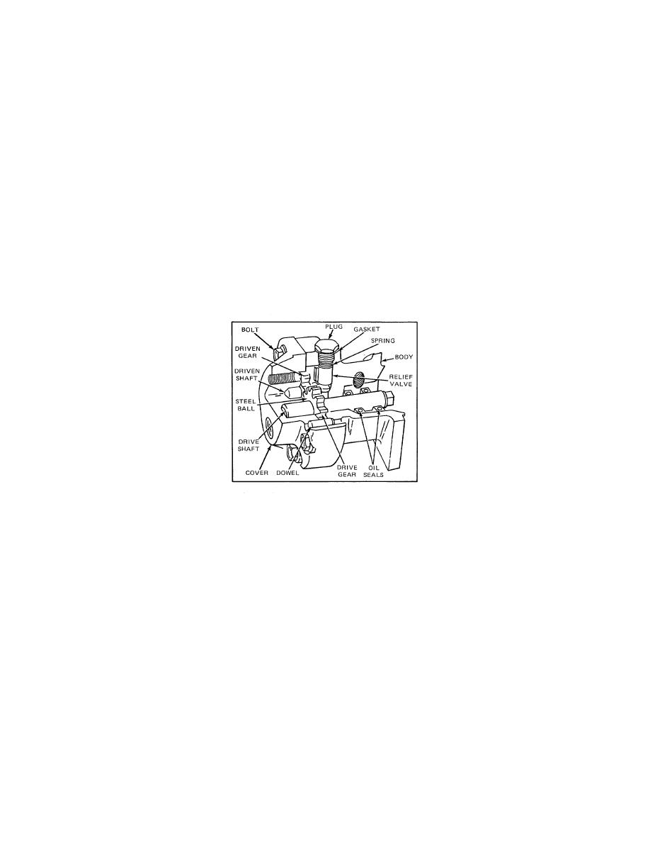
The positive displacement gear-type fuel pump (Fig. 1) transfers fuel from the supply tank to the fuel injectors.
The pump circulates an excess supply of fuel through the injectors which purges the air from the system and
cools the injectors. The unused portion of fuel returns to the fuel tank by means of a fuel return manifold and
fuel return line.
On the in-line engine, the fuel pump is mounted on the governor weight housing and is driven through a drive
coupling by the governor weight shaft.
Certain engine applications use a high-capacity fuel pump with 3/8-inch-wide gears to increase fuel flow and
reduce fuel spill temperature. The high-capacity fuel pump and the standard fuel pump with 1/4-inch-wide
gears are not completely interchangeable; therefore, when replacing a standard pump with a high-capacity
pump, the appropriate fuel lines and connections must be used.
The fuel pump cover and body are positioned by two dowels.
The dowels aid in maintaining gear shaft
alignment.
Figure 1. Typical Fuel Pump Assembly.
The mating surfaces of the pump body and cover are perfectly flat ground surfaces. No gasket is used
between the cover and body since the pump clearances are set up on the basis of metal-to-metal contact. A
very thin coat of sealant provides a seal against any minute irregularities in the mating surfaces. Cavities in the
pump cover accommodate the ends of the drive and driven shafts.
The fuel pump body is recessed to provide running space for the pump gears (Fig. 2). Recesses are also
provided at the inlet and outlet positions of the gears. The small hole A permits the fuel oil in the inlet side of
the pump to lubricate the relief valve at its outer end and to eliminate the possibility of a hydrostatic lock which
would render the relief valve inoperative. Pressurized fuel contacts the relief valve through hole B and
provides for relief of excess discharge pressures. Fuel reenters the inlet side of the pump through hole C when
the discharge pressure is great enough to move the relief valve back from its seat. Part of the relief valve may
be seen through hole C. The cavity D provides escape for the fuel oil which is squeezed out of the gear teeth
as they mesh together on the discharge side of the pump. Otherwise, fuel trapped at the root of the teeth would
tend to force the gears apart, resulting in undue wear on the gears, shafts, body, and cover.
Two oil seals are pressed into the bore in the flanged side of the pump body to retain the fuel oil in the pump
and the lubricating oil in the blower timing gear compartment (Fig. 1). The oil seals are installed with the lips of
the seals facing toward the flanged end of the pump body. A small hole E (Fig. 2) serves as a vent
passageway in the body, between the inner oil seal
244
