
TM 5-3895-346-14
CAMSHAFT AND BEARINGS
ENGINE OVERHAUL
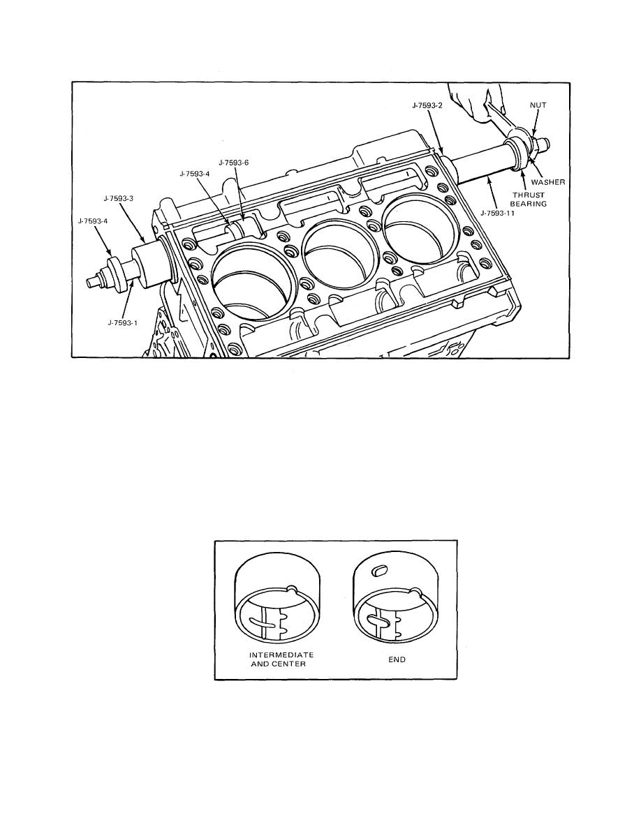
Figure 6. Installing Intermediate Camshaft Bearing
3. Then, with the unthreaded end of shaft J 7593-1 started through the pilot, push the shaft through the
entire length of the block bore.
4. Slide installer J 7593-6 on the shaft until the locating pin registers with the notch in the bearing. Then
slide installer J 7593-3 or J 7593-15 on the shaft with the large diameter inserted into the end of the block
bore. Refer to C and note of Fig. 9.
5. Next, place a spacer (if required), thrust washer, plain washer, and hex nut over the threaded end of
the puller.
6. Align the shaft in such a way that a C-washer J 7593-4 can be inserted in a groove in the shaft adja-
cent to installer J 7593-6.
Figure 7. Camshaft and Balance Shaft Bearing Identification
7. Place a C-washer in the groove near the end of the shaft and, using a suitable wrench on the hex nut,
draw the bearing into place until the Cwasher butts up against installer J 7593-3 and prevents the shaft from
further movement.
177
