
TM 5-3895-346-14
FLYWHEEL HOUSING
ENGINE OVERHAUL
IMPORTANT
It is very important that all old gasket material be thoroughly removed from the flywheel housing and the end
plate, otherwise runout of the pilot and face of the housing may be affected when the housing is installed on the
engine.
Remove and discard the crankshaft rear oil seal. Install a new oil seal as outlined in Crankshaft Oil Seals.
Install Flywheel Housing
1.
Lubricate the gear train teeth with clean engine oil.
2.
Affix a new flywheel housing gasket to the rear face of the cylinder block rear end plate. Affix the
small (7/8 inch diameter) gasket near the top of the end plate.
3.
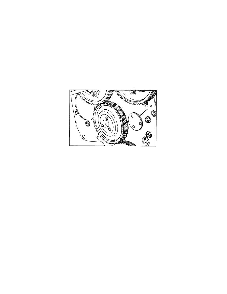
If the flywheel housing has an integral cast hub, install a flywheel housing-to-end plate shim (0.015
inch thick). Use grease to hold the shim to the cylinder block rear end plate (Fig. 2).
4.
Coat the lip of the crankshaft oil seal lightly with engine oil (single-lip seal) or vegetable shorten-
ing (double-lip seal). Do not scratch or nick the sealing edge of the oil seal.
Figure 2. Location of Shim
5.
Thread two pilot studs J 7540 into the cylinder block to guide the housing in place (Fig. 1). On in-
line engines, to pilot the oil seal on the crankshaft successfully, use oil seal expander J 9769 (standard size
seal) or J 21278-01 (oversize seal) on the end of the crankshaft.
6.
With the housing suitably sup- ported, position it over the crankshaft and up against the cylinder
block rear end plate and gasket(s). Remove the oil seal expander.
7.
Install all the flywheel housing bolts, lockwashers, flat washers, and copper washers in their proper
location, finger tight. Remove the pilot studs.
NOTE
If the engine is equipped with a clutch housing, do not install the six bolts
numbered 7 through 12 (Fig. 3) until the clutch housing is installed.
8.
On an in-line right-hand rotation engine, start at No. 1 and draw the bolts up snug in the sequence
shown in Fig. 3.
9.
Refer to Fig. 4 for the final bolt tightening sequence on an in-line engine. Then start at No. 1 and
tight- en the bolts to the specified torque.
a.
Tighten the 5/16-18 bolts (No. 11 and 12) to 19-23 lb ft (26-31 Nm) torque and the 3/8-16
bolts (No. 7 through 10) to 40-45 lb ft (54-61 Nm) torque. Tighten the remaining 3/8-16 and 3/8-24 bolts to 25-
30 lb ft (34-41 Nm) torque.
NOTE
Prior to Engine Serial Number 4D-103, the bolts numbered 7 through 12 in Fig. 3
were all 5/16-18 bolts and must be tightened to 19-23 lb ft (26-31 Nm) torque
136
