
TM 5-3895-346-14
MAIN BEARINGS
ENGINE OVERHAUL
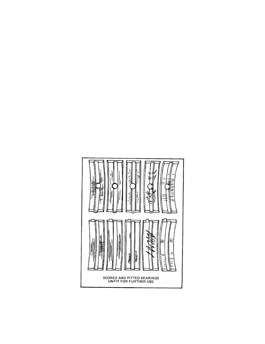
Af ter removal, clean the bearings and inspect them for scoring, pitting, flaking, etching, loss of babbitt, or signs
of overheating (Fig. 4). The lower bearing shells, which carry the load, will normally show signs of dis- tress
before the upper bearing shells.
Inspect the backs of the bearing shells for bright spots which indicate they have been moving in the bearing
caps or bearing supports. If such spots are present, discard the bearing shells.
Measure the thickness of the bearing shells at point C, 90from the parting line, as shown in Fig. 5 and 6. Tool
J 4757, placed between the bearing shell and a micrometer, will give an accurate measurement. The bearing
shell thickness will be the total thickness of the steel ball in the tool and the bearing shell, less the diameter of
the ball.
This is the only practical method for measuring the bearing thickness, unless a special micrometer is available
for this purpose. The minimum thickness of a worn standard main bearing shell is .1230 inch and, if any of the
bearing shells are thinner than this dimension, replace all of the bearing shells. A new standard bearing shell
has a thickness of .1245 to .1250 inch.
In addition to the thickness measure- ment, check the clearance between the main bearings and the crankshaft
journals. This clearance may be deter- mined with the crankshaft in place by means of a soft plastic measuring
strip which is squeezed between the journal and the bearing (refer to Shop Notes). With the crankshaft
removed, measure the outside diameter of the crankshaft main bearing journals and the inside diameter of the
main bearing shells Figure 4. Comparison of Main Bearing Shells
Figure 4. Comparison of Main Bearing Shells
121
