
TM 5-3895-346-14
ENGINE OVERHAUL
CRANKSHAFT
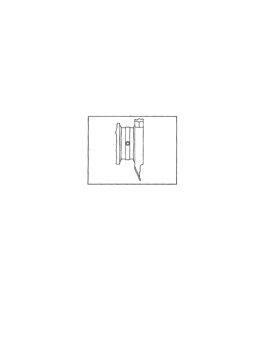
Used crankshafts will sometimes show a certain amount of ridging caused by the groove in the upper main
bearing shell or lower connecting rod bearing shell (Fig. 3). Ridges exceeding 0.0002 inch must be removed.
If the ridges are not removed, localized high-unit pressures on new bearing shells will result during engine
operation.
The ridges may be removed by working crocus cloth, wet with fuel oil, around the circumference of the
crankshaft journal. If the ridges are greater than 0.0005 inch, first use 120-grit emery cloth to clean up the
ridge, 240-grit emery cloth for finishing, and wet crocus cloth for polishing. Use of a piece of rawhide or other
suitable rope wrapped around the emery cloth or crocus cloth and drawn back and forth will minimize the
possibility of an out-of-round condition developing (keep the strands of rawhide apart to avoid bind). If rawhide
or rope is not used, the crankshaft should be rotated at intervals. If the ridges are greater than 0.001 inch, the
crankshaft may have to be reground.
Carefully inspect the front and rear end of the crankshaft in the area of the oil seal contact surface for evidence
of a rough or grooved condition. Any imperfections of the oil seal contact surface will result in oil leakage at
this point.
Figure 3. Typical Ridging of Crankshaft
Slight ridges on the crankshaft oil seal contact surface may be cleaned up with emery cloth and crocus cloth in
the same manner as detailed for the crankshaft journals. If the crankshaft cannot be cleaned up satisfactorily,
the oil seal may be repositioned in the flywheel housing and front cover as outlined in Crankshaft and Oil Seals.
Check the crankshaft thrust surfaces for excessive wear or grooving. If only slightly worn, the surfaces may be
dressed with a stone. Otherwise it will be necessary to regrind the thrust surfaces.
Check the oil pump drive gear and the crankshaft timing gear for worn or chipped teeth. Replace the gears if
necessary.
Inspect the crankshaft for cracks as outlined under Inspection for Cracks.
Crankshaft Measurements
Support the crankshaft on its front and rear journals on V-blocks or in a lathe, and check the alignment at the
adjacent intermediate main journals with a dial indicator.
On 4-cylinder in-line crankshafts, the maximum runout on the intermediate journals must not exceed 0.002 inch
total indicator reading.
Measure all of the main and connecting rod bearing journals (Fig. 6). Measure the journals at several places
on the circumference so that taper, out-of-round and bearing clearances can be determined. If the crankshaft
is worn so that the maximum connecting rod journal-to-bearing shell clearance
107
