
EB 1185-10
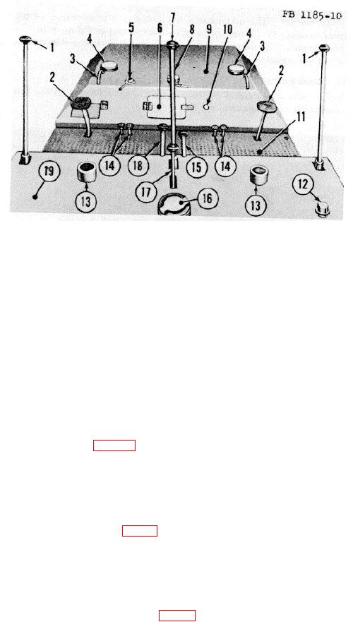
1
Forward and reverse clutch lever
11
Operator's platform
2
Brake pedal
12
Hydraulic tank filler cap
3
Front housing lifting eye
13
Operator's seat post
4
Sprinkler tank filler cap
14
Sprinkler pedals
5
Fuel gage transmitter
15
Gear shift lever
6
Instrument panel door
16
Radiator filler cap
7
Steering lever
17
Governor control lever
8
Fuel tank cap
18
Master clutch lever
9
Front housing
19
Rear housing
10
Magneto switch
Figure 10. Road roller, top view.
14. Gearshift Lever
a. Location. The gearshift lever (15, Fig. 10) is located on the rear housing (19), at the right side of the steering
lever (7).
b. Purpose. The gearshift lever is used for low and high-gear shifting.
15. Governor Control Lever
a. Location. The governor control lever (17, fig. 10) is located on the rear housing (19), behind the steering lever (7).
b. Purpose. The governor control lever adjusts the engine speed to compensate for momentary operational load
demands.
16. Sprinkler Control Pedals
a. Location. The dual sprinkler control pedals (14, fig. 10) are located on the left and right sides of the operator's
platform (11).
b. Purpose. The sprinkler control pedals operate the valves which open and close the sprinkler system.
23