
TM 5-3895-379-23
TROUBLESHOOTING PROCEDURES - CONTINUED
0006 00
Table 2. Electrical Troubleshooting Procedures - Continued.
MALFUNCTION
TEST OR INSPECTION
CORRECTIVE ACTION
WARNING
Remove all jewelry such as rings, dog tags and bracelets. If jewelry
contacts electrical connection, a direct short may occur resulting in
injury or death and damage to equipment.
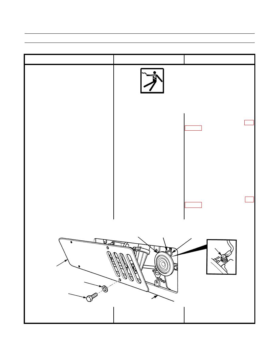
1. Check for power at horn. Remove If 24-28 Vdc are measured, ground is
11. Horn Does Not Work.
four screws, washers, and cover OK. Replace horn assembly (WP
from front support assembly. 0102 00).
Have an assistant turn battery
disconnect switch and engine
start switch ON, and press down
horn switch (TM 5-3895-379-
10). Set multimeter to measure
Vdc. Touch positive (+) probe of
multimeter to terminal 1 (wire
322-GY) and negative (-) probe
of multimeter to good ground.
If less than zero ohms are measured,
2. Check for good ground at horn.
Loosen screw and remove wire
ground is bad. Repair or replace
200-BK from horn assembly. Set
wiring and connectors from horn to
multimeter to read ohms. Touch
ground connection at frame (WP
positive (+) probe of multimeter
to 200-BK and negative (-) probe
of multimeter to good ground.
WIRE
HORN
322-GY
WIRE 200-BK
SCREW
COVER
WASHER
SCREW
SUPPORT ASSEMBLY
401-212

