
TM 5-3895-379-23
TROUBLESHOOTING PROCEDURES - CONTINUED
0006 00
Table 2. Electrical Troubleshooting Procedures - Continued.
MALFUNCTION
TEST OR INSPECTION
CORRECTIVE ACTION
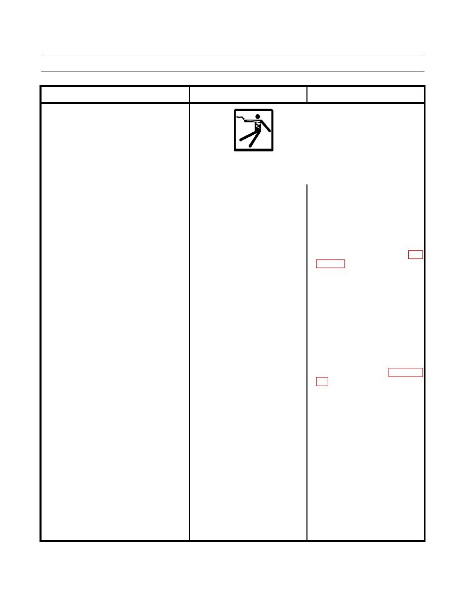
WARNING
Remove all jewelry such as rings, dog tags and bracelets. If jewelry
contacts electrical connection, a direct short may occur resulting in
injury or death and damage to equipment.
1. Battery disconnect and start 1. If 24 to 28 Vdc are not measured
10. Work Lights and Gauge Lights Do
Not Operate.
switches in ON position (TM 5-
at input terminal (wire 112-PU),
3895-379-10). Check for power
turn engine start switch and battery
to lights circuit breaker. Remove
disconnect switch to OFF position
nine screws and washers remove
(TM 5-3895-379-10). Repair or
panel from operator station. Turn
replace wire 112-PU and
battery disconnect switch and
connectors from main relay to
engine start switch to ON position
alternator circuit breaker (WP
(TM
5-3895-379-10).
Set
multimeter to measure Vdc.
Touch positive (+) probe of 2. If 24 to 28 Vdc are measured at
input terminal (wire 112-PU), go
multimeter to input terminal
to Step 2.
(wire 122-PU) of lights circuit
breaker and negative (-) probe of
multimeter to good ground.
2. Battery disconnect and start 1. If 24 to 28 Vdc are not measured
switches in ON position (TM 5-
at output terminal (wire 114-GN),
3895-379-10). Check for power
turn engine start switch and battery
at lights circuit breaker. Press
disconnect switch to OFF position
circuit breaker button to reset.
(TM 5-3895-379-10). Replace
Touch positive (+) probe of
lights circuit breaker (WP 0086
multimeter to output terminal
(wire 114-GN) and negative (-)
probe of multimeter to good
ground.
2. If 24 to 28 Vdc are measured at
output terminal (wire 114-GN), go
to Step 3.

