
TM 5-3895-379-23-2
0244
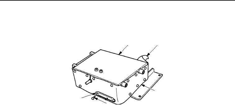
ASSEMBLY - Continued
24.
Install boot (Figure 22, Item 2) and plate (Figure 22, Item 5) on upper housing assembly (Figure 22, Item 1)
and lower housing assembly (Figure 22, Item 3) with 24 fasteners (Figure 22, Item 4).
1
2
3
5
4
M0800SWR
Figure 22.
Seat Suspension Assembly.
25.
Position torsion spring (Figure 23, Item 4) and one link (Figure 23, Item 1) on rear mounting bracket of upper
housing assembly (Figure 23, Item 6).
26.
Install ends of torsion spring (Figure 23, Item 4) in right-side of upper housing assembly (Figure 23, Item 6)
and link (Figure 23, Item 1).
27.
Apply sealing compound to threads of bolts (Figure 23, Item 3).
28.
Install torsion spring (Figure 23, Item 4) and link (Figure 23, Item 1) on upper housing assembly
(Figure 22, Item 6) with two bolts (Figure 22, Item 3), using socket wrench screwdriver attachment.
29.
Position link (Figure 23, Item 2) on link (Figure 23, Item 1) on right-side of seat suspension assembly
(Figure 23, Item 5) ensuring that hole is fully seated on shoulder of stud.
30.
Apply sealing compound to threads of locknut (Figure 23, Item 8).
31.
Install link (Figure 23, Item 2) on link (Figure 23, Item 1) with washer (Figure 23, Item 7) and new locknut
(Figure 23, Item 8).
03/15/2011Rel(1.8)root(maintwp)wpno(M00182)

