
TM 5-3895-379-23-2
0244
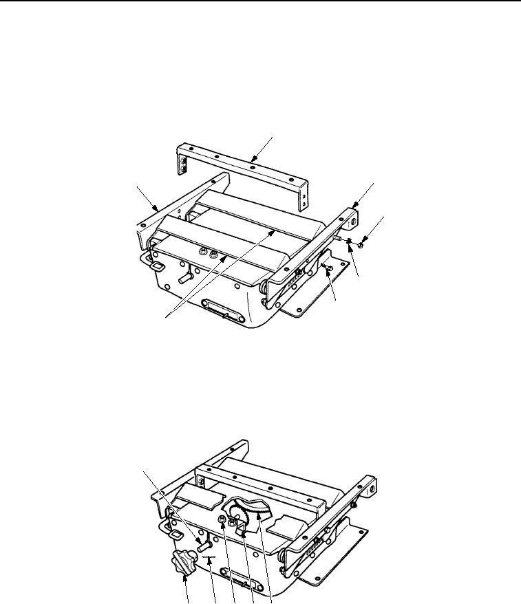
ASSEMBLY - Continued
46.
Install left angle assembly (Figure 27, Item 3) and right angle assembly (Figure 27, Item 1) on two links
(Figure 27, Item 7) with four washers (Figure 27, Item 5) and new locknuts (Figure 27, Item 4). Tighten nuts
to 84-192 lb-in. (9-22 Nm).
47.
Install channel (Figure 27, Item 2) from left angle assembly (Figure 27, Item 3) and right angle assembly
(Figure 27, Item 1) with four bolts (Figure 27, Item 6). Tighten bolts to 84-192 lb-in. (9-22 Nm).
2
3
1
4
5
6
7
M0805SWR
Figure 27.
Seat Suspension Assembly.
48.
Install knob (Figure 28, Item 6) on bevel gear (Figure 28, Item 1) with spring pin (Figure 28, Item 5).
49.
Adjust angle bracket (Figure 28, Item 3) so that bevel gear (Figure 28, Item 1) fits snugly against gear assembly
(Figure 28, Item 2) and knob (Figure 28, Item 6) feels firm.
50.
Tighten locknuts (Figure 28, Item 4).
1
6
5
4
3
2
M0806SWR
Figure 28.
Seat Suspension Assembly.
END OF TASK
03/15/2011Rel(1.8)root(maintwp)wpno(M00182)

