
TM 5-3895-379-23-2
0242
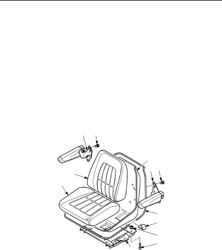
ASSEMBLY - Continued
NOTE
Seat assembly must be moved to full forward or full rear position to install screws and nuts
holding seat supports to adjuster assembly.
3.
Install seat shell (Figure 5, Item 3) on seat adjuster (Figure 5, Item 9) with four screws (Figure 5, Item 8) and
nuts (Figure 5, Item 7).
4.
Position seat cushion (Figure 5, Item 10) and backrest cushion (Figure 5, Item 11) in seat shell
(Figure 5, Item 3).
NOTE
Seat cushion material must be wrapped around seat shell for proper installation.
5.
Secure seat cushion (Figure 5, Item 10) and backrest cushion (Figure 5, Item 11) in seat shell
(Figure 5, Item 3) using trim (Figure 5, Item 5) and clip (Figure 5, Item 6).
6.
Install right arm assembly (Figure 5, Item 1) on seat shell (Figure 5, Item 3) with three screws
(Figure 5, Item 2).
7.
Install left arm assembly (Figure 5, Item 4) on seat shell (Figure 5, Item 3) with three screws
(Figure 5, Item 2).
1
2
3
2
4
11
10
5
6
7
8
9
M1174SWR
Figure 5. Seat Assembly Assembly.
03/15/2011Rel(1.8)root(maintwp)wpno(M00180)

