
TM 5-3895-379-23-2
0244
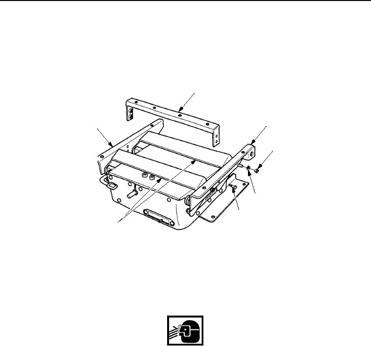
DISASSEMBLY - Continued
4.
Remove four bolts (Figure 2, Item 6) and channel (Figure 2, Item 2) from left angle assembly
(Figure 2, Item 3) and right angle assembly (Figure 2, Item 1).
5.
Remove four locknuts (Figure 2, Item 4), washers (Figure 2, Item 5), left angle assembly (Figure 2, Item 3),
and right angle assembly (Figure 2, Item 1) from two links (Figure 2, Item 7). Discard locknuts.
2
3
1
4
5
6
7
M0781SWR
Figure 2. Seat Suspension Disassembly.
6.
Remove two locknuts (Figure 3, Item 5), washers (Figure 3, Item 4), and link (Figure 3, Item 1) on left-side of
seat suspension assembly (Figure 3, Item 3) from two links (Figure 3, Item 2). Discard locknuts.
7.
Remove two locknuts (Figure 3, Item 5) and washers (Figure 3, Item 4) on right-side of seat suspension
assembly (Figure 3, Item 3) from two links (Figure 3, Item 2). Discard locknuts.
WARNING
Height adjustment lever is under spring tension. Wear eye protection and use caution when
removing height adjustment lever. Failure to follow this warning may cause injury.
8.
While assistant lifts up on height adjustment lever (Figure 3, Item 6), remove link (Figure 3, Item 1) on
right-side of seat suspension assembly (Figure 3, Item 3) from two links (Figure 3, Item 2).
03/15/2011Rel(1.8)root(maintwp)wpno(M00182)

