
TM 5-3895-346-14
AXLE
DRIVE CARE AND MAINTENANCE
11. Install key, press flange on taper, and install washer and pinion shaft nut.
12. Tighten to the correct torque and install cotter key.
CAUTION
Do not back off nut to align cotter key holes.
ASSEMBLE DIFFERENTIAL AND BEVEL GEAR
1. Rivet bevel gear to case half with new rivets.
NOTE
If a new gear or differential case is to be used in the assembly, the rivet holes in the gear
and case should be checked for alignment and line reamed if necessary. The gear must
be tight on the case pilot and riveted flush with the differential case flange. Check with a
0.002-inch feeler gauge.
Rivets should not be heated, but should be upset cold. When the correct rivet and rivet
set is used the head being formed will be at least 1/8 inch larger in diameter than the
rivet hole.
The head will then be approximately the same height as the preformed head. The
formed head should not exceed 1/16 inch less than the preformed head as excessive
pressure will cause distortion of the case holes and result in gear eccentricity.
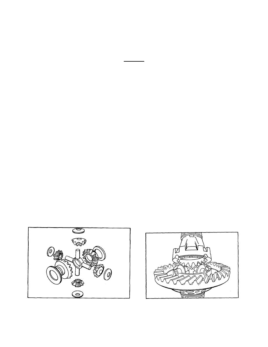
2. Lubricate differential case inner walls and all component parts with axle lubricant.
3. Position thrust washer and side gear in bevel gear and case half assembly.
4. Place spider with pinions and thrust washers in position (refer to Fig. 6 and 7).
5. Install component side gear and thrust washer.
6. Align mating marks, position component case half, and draw assembly together with four bolts or capscrews
equally spaced.
Figure 6.
Figure 7.
629

