
TM 5-3895-346-14
AXLE
DRIVE CARE AND MAINTENANCE
3. Inspect the differential assembly for the following:
a. Pitted, scored, or worn thrust surfaces of differential case halves, thrust washers, spider trunnions,
and differential gears.
Thrust washers must be replaced in sets. The use of a combination of old and new washers will result in
premature failure.
b. Wear or damage to the differential pinion and side gear teeth.
Always replace differential pinions and side gears in sets.
4. Spur pinions for wear or damage to teeth.
5. Check end of pinion for indications of brinelling caused by worn splines. Replace the parts if the splines of
the pinion and/or thru-shaft are worn, permitting movement of the pinion on the thru-shaft.
6. Axle shafts for indications of torsional fractures and runout. Axle shafts should be inspected between
centers to ascertain the amount of runout of the ground surfaces. Runout at the shaft flange and splines should
not exceed . 005-inch total indicator reading.
REPAIR
1. Replace all worn or damaged parts. Hex nuts with rounded corners, all lockwashers, oil seals, and gaskets
should be replaced at the time of overhaul.
Use only genuine Rockwell-Standard parts for satisfactory service. For example, using gaskets of foreign
material generally leads to mechanical trouble due to variations in thickness and the inability of certain
materials to withstand compression, oil, etc.
2. Remove nicks, mars, and burrs from machined or ground surfaces. Threads must be clean and free to
obtain accurate adjustment and correct torque. A fine mill file or India stone is suitable for this purpose. Studs
must be tight prior to reassembling the parts.
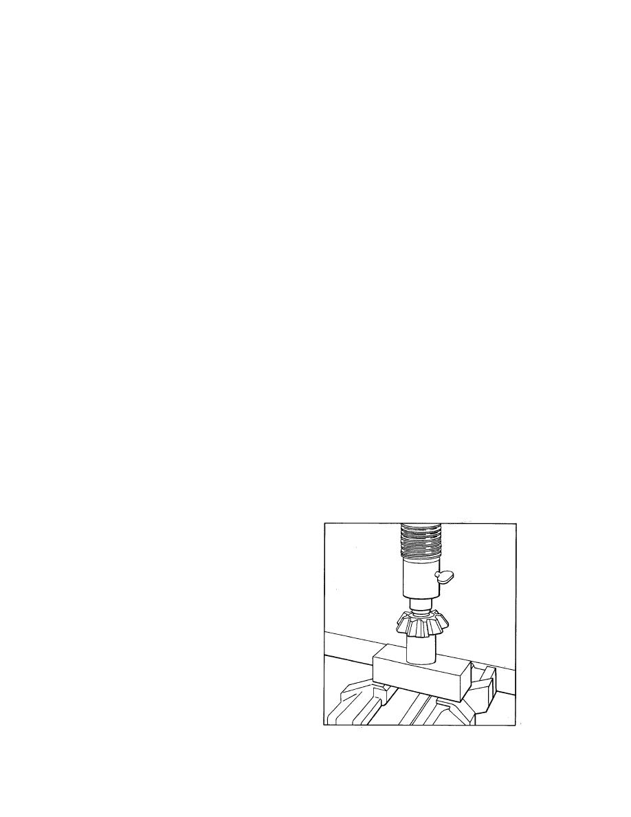
3. If necessary, install new differential pinion bushings where used as follows:
a. Remove worn bushing. The bushing may be
split with a hacksaw and the halves easily
removed.
b. Remove burrs or sharp corner from inner edge
of pinion bore to prevent shearing or buckling of
bushing on installation.
c. Place pinion on anvil. Position bushing in inner
end of pinion bore and press squarely into
position. Use adaptor with correct size offset to fit
bushing (refer to Fig. 10).
Figure 10.
625

