TM 5-3895-383-24
Vibratory System
LOW AMPLITUDE
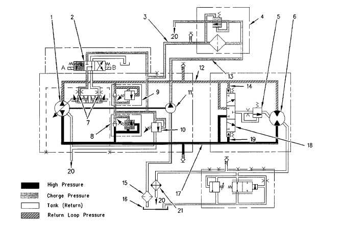
Illustration 18
Vibratory system (LOW AMPLITUDE)
(1) Vibratory pump. (2) Directional control valve. (3) Charge pressure line. (4) Oil filter (vibratory charge pressure). (5) Flushing relief valve. (6)
Vibratory motor. (7) Orifices. (8) High pressure relief valve. (9) High pressure relief valve. (10) Charge pressure relief valve. (11) Charge
pump.
(12)
Closed
circuit
loop
line.
(13)
Line.
(14)
Pilot
passage.
(15)
Hydraulic
oil
strainer.
(16) Hydraulic oil tank. (17) Closed circuit loop line. (18) Flushing valve. (19) Plot passage. (20) Lines to the return manifold (three). (21) Oil
cooler. (A) Solenoid. (B) Solenoid.
Charge pressure oil flows through passage (3) to the directional
control valve (2) when the engine is operating.
The solenoid coil (A) on the control valve (2) receives an
electrical current when the following conditions occur:
The vibratory control switch which is located on the
propel lever is in the ON position.
LOW AMPLITUDE has been activated. Low amplitude
is located on the vibratory amplitude control. The
vibratory amplitude control is located on the operator
control console.
Engine speed is high enough to close the vibratory
lockout switch.
The electrical current to solenoid (A) causes the spool in the
directional control valve (2) to shift to the position in illustration
(2). This allows control oil from passage (3) to be directed to
the proper side of the servo in pump (1). The control oil moves
the swashplate to the maximum angle for high amplitude.
Orifices (7) control the oil flow to the pump servo for smooth
movement of the swashplate.
11-21