TM 5-3895-383-24
Flushing Valve (Drum)
SMCS Code: 4352; 5058; 5066
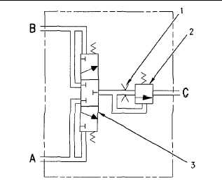
Illustration 52
Drive motor flushing valve
(1) Orifice. (2) Relief valve. (3) Shuffle valve spool. (A)
Closed loop circuit line. (B) Closed loop circuit line. (C) Flush
port.
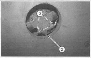
Illustration 53
Drive motor flushing valve
(2) Relief valve. (3) Shuttle valve spool.
The drive motor flushing valve is located in the closed loop
circuit of the drum drive motor. Lines (A) and (B) represent the
two loops of the closed loop circuit. The operation of the
propel pump in either FORWARD or REVERSE regulates the
direction of flow in the loop. The direction of flow in the loop
determines whether a line is high pressure or low pressure.
Pilot pressure on the high pressure side shifts shuttle valve (3).
The low pressure side opens to relief valve (2). The relief
valve is set at 1800 kPa (261 psi). The return oil on the low
pressure side of the closed loop flows across the relief valve.
After passing through the relief valve, the oil flows through port
(C) to the motor case. This oil cools the motor and the oil
flushes the motor. The amount of flushing oil is controlled by
the
size
of
the
orifice
(1).
The
orifice
provides
10 L/min (2.6 US gpm) of flushing flow.
10-47